Multi-Function Prototyping / Expansion Shield For Arduino UNO LEONARDO MEGA2560
Multi-Function Prototyping / Expansion Shield For Arduino UNO LEONARDO MEGA2560
Couldn't load pickup availability
📋 Overview
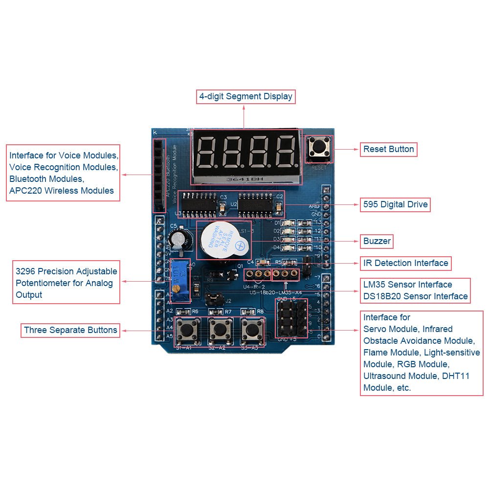
The Multifunction Prototyping / Expansion Shield is an Arduino-compatible development board packed with on-board components and expansion headers. It plugs directly onto your Arduino UNO R3, Leonardo, or MEGA2560 using standard R3-type headers — no wiring or breadboard needed to get started.
This shield is ideal for beginners who want to experiment and learn without the hassle of wiring individual components on a breadboard. It's also a great general-purpose prototyping and development platform for more advanced users who need quick access to common I/O devices like displays, buttons, LEDs, and sensor interfaces.
Besides the range of components fitted directly to the shield, there are also numerous expansion headers providing convenient interfaces for external modules and components such as temperature sensors, infrared receivers, servos, and serial communication modules.
⭐ Key Features
- Plug-and-Play Compatibility: Seamlessly connects with Arduino UNO R3, Leonardo, and MEGA2560 controllers via standard R3 headers
- 4-Digit 7-Segment LED Display: Driven by two cascaded 74HC595 serial-to-parallel shift registers for efficient pin usage
- 4× Surface Mount LEDs: In a parallel configuration, convenient for debugging and status indication (active LOW on pins D10–D13)
- 10K Precision Potentiometer: #3296 multi-turn analog adjustable trimpot on pin A0 for controlling LED brightness, voltage adjustment, and more
- 3× Independent Push Buttons: Active LOW buttons on pins A1, A2, and A3 for convenient control input and user interaction
- Integrated Piezo Buzzer: Transistor-driven buzzer on pin D3 for audible alerts and tone generation
- DS18B20 Temperature Sensor Interface: One-wire digital temperature sensor header on pin A4 (sensor not included)
- LM35 Temperature Sensor Interface: Integrated circuit analog temperature sensor header on pin A4 (sensor not included)
- Infrared Receiver Interface: Header on pin D2 for IR receiver modules such as the 1838B (receiver not included)
- Servo Interface: Header for connecting a standard hobby servo motor
- Serial Interface Header: GND, 5V, RX (D0), and TX (D1) connections for serial modules such as APC220 radio, Bluetooth, voice modules, and voice recognition modules
- Free PWM Pins Header: Breakout header for unused pins D5, D6, D9, and A5 — available for your own components
- On-Board Reset Button: Convenient reset for your Arduino without reaching under the shield
📌 Pinout / Pin Mapping
All on-board components are hard-wired to specific Arduino pins. Understanding this pin mapping is essential when writing your sketches.
On-Board Component Pin Assignments
| Component | Arduino Pin(s) | Notes |
|---|---|---|
| 7-Segment Display — Latch | D4 | 74HC595 latch (RCLK) |
| 7-Segment Display — Clock | D7 | 74HC595 clock (SRCLK) |
| 7-Segment Display — Data | D8 | 74HC595 serial data (SER) |
| LED 1 | D13 | Active LOW |
| LED 2 | D12 | Active LOW |
| LED 3 | D11 | Active LOW |
| LED 4 | D10 | Active LOW |
| Potentiometer | A0 | 10K multi-turn trimpot, analog input |
| Button S1 | A1 | Active LOW (pressed = LOW) |
| Button S2 | A2 | Active LOW (pressed = LOW) |
| Button S3 | A3 | Active LOW (pressed = LOW) |
| Piezo Buzzer | D3 | Digital on/off via transistor driver |
| DS18B20 / LM35 Sensor | A4 | Shared temperature sensor header |
| Infrared Receiver | D2 | IR receiver module header |
| Serial Header (APC220) | D0 (RX), D1 (TX) | Shared with Arduino USB serial |
| Reset Button | GND (Reset) | Resets the Arduino board |
Free Pins (Available for Your Projects)
| Pin | Notes |
|---|---|
| D5 | PWM capable |
| D6 | PWM capable |
| D9 | PWM capable (also commonly used for the servo interface) |
| A5 | Analog input / digital I/O |
📝 Note: Pins D0 and D1 are shared with the Arduino's USB serial connection. If you use the serial header (e.g., for an APC220 or Bluetooth module), you will not be able to use the Serial Monitor at the same time. Disconnect serial modules before uploading new sketches.
📐 Specifications
| Parameter | Value |
|---|---|
| Compatibility | Arduino UNO R3, Leonardo, MEGA2560 (R3-type headers) |
| Operating Voltage | 5V DC (powered via Arduino board) |
| Display | 4-digit 7-segment LED (common cathode) |
| Display Driver | 2× 74HC595 serial-to-parallel shift registers |
| LEDs | 4× surface mount (active LOW, pins D10–D13) |
| Buttons | 3× tactile push buttons (active LOW, pins A1–A3) |
| Buzzer | Piezo buzzer with transistor driver (pin D3) |
| Potentiometer | #3296 10KΩ multi-turn trimpot (pin A0) |
| Sensor Interfaces | DS18B20 (digital), LM35 (analog) — shared header on A4 |
| IR Receiver Interface | Pin D2 — compatible with 1838B IR receiver |
| Servo Interface | 3-pin header (Signal, VCC, GND) |
| Serial Interface | D0 (RX), D1 (TX), 5V, GND — for APC220, Bluetooth, etc. |
| Free Pins | D5, D6, D9 (PWM), A5 |
| Connector Type | Standard Arduino R3-type pin headers |
| Dimensions | Approx. 66 × 54 × 21 mm (2.6 × 2.1 × 0.83 inches) L × W × H |
🔌 Expansion Headers / External Connections
The shield provides several expansion headers for connecting external modules and sensors. These headers break out the appropriate power and signal pins for easy plug-in connections.
DS18B20 / LM35 Temperature Sensor Header
The temperature sensor header connects to Arduino pin A4. It supports either a DS18B20 one-wire digital sensor or an LM35 analog sensor (use one at a time, not both simultaneously). The DS18B20 requires the OneWire and DallasTemperature libraries.
Infrared Receiver Header
The IR receiver header connects to Arduino pin D2. It is compatible with the 1838B infrared receiver module. The IRremote library is required for decoding IR signals.
⚠️ Warning: The IR header pinout is compatible with the 1838B IR receiver. It is not directly compatible with the SFH506-38 receiver — always check the schematic before connecting external components.
Servo Interface
The servo header provides a convenient 3-pin connection (Signal, VCC, GND) for a standard hobby servo. The signal pin is typically routed to one of the free PWM pins on the expansion header.
Serial / APC220 Header
The serial header provides GND, 5V, RX (D0), and TX (D1) connections for serial communication modules such as APC220 radio modules, Bluetooth modules, voice modules, and voice recognition modules.
⚠️ Warning: The serial header shares pins D0 and D1 with the Arduino's USB serial connection. Disconnect any serial module from this header before uploading sketches, or you may experience upload errors.
📦 What's in the Box
- 1× Multi-Function Prototyping / Expansion Shield for Arduino
Arduino board, external sensors (DS18B20, LM35, IR receiver), and servo motors are not included.
🛒 What You'll Need
- Arduino-compatible UNO R3, Leonardo, or MEGA2560 — The host controller board (required)
- USB Cable — To connect your Arduino to a computer for programming
- Arduino IDE — Free software for writing and uploading sketches (download here)
- External Sensors (optional) — DS18B20 or LM35 temperature sensor, 1838B IR receiver, servo motor, or serial communication module to use with the expansion headers
🔌 Compatible With
- Arduino UNO R3
- Arduino Leonardo
- Arduino MEGA2560
- Other Arduino-compatible boards with R3-type header layout
🎯 Typical Applications
- Learning Arduino programming with built-in I/O components
- Prototyping user interfaces with buttons, LEDs, and 7-segment display
- Temperature monitoring projects (with external DS18B20 or LM35 sensor)
- IR remote control projects (with external 1838B receiver)
- Alarm and notification systems using the buzzer
- Servo control experiments
- Wireless communication prototyping via the serial header
- Rapid prototyping and proof-of-concept development
- Classroom and workshop instruction for Arduino concepts
⚠️ Important Notes
- USB connector clearance: Ensure that the LED display pins on the back of the shield do not touch and short against the Arduino UNO board's USB connector. You may need to place an insulator (such as a piece of electrical tape or a small piece of cardboard) between the two to prevent contact.
- Active LOW LEDs: The four on-board LEDs are active LOW — write LOW to turn them ON and HIGH to turn them OFF. This is the opposite of what many beginners expect.
- Active LOW buttons: The three push buttons read LOW when pressed and HIGH when released. Use INPUT_PULLUP mode or the shield's built-in pull-up resistors.
- Pin conflicts: Since the on-board components are hard-wired to specific pins, those pins are not available for other uses while the shield is attached. Plan your projects around the free pins (D5, D6, D9, A5).
- Servo power: If using a servo, be aware that powering it directly from the Arduino's 5V pin may cause voltage drops or resets under heavy load. For larger servos, consider an external power supply.
- Temperature sensors not included: The DS18B20 and LM35 temperature sensors are not included with the shield and must be purchased separately.
- Serial pin sharing: Pins D0 and D1 are shared with the Arduino's USB serial connection. Disconnect serial modules before uploading new sketches.
📄 Documentation & Resources
Documentation
Full wiring diagrams, sample code, and troubleshooting guides are available at the Envistia Mall product support website.
Sold and supported by Envistia Mall. Ships from the USA. For wiring diagrams, sample code, and troubleshooting, see the User Guide. The manufacturer and Envistia LLC (dba Envistia Mall) are not responsible for any damages or losses resulting from the use of this product. Always follow proper electrical safety practices when working with electronic components. Specifications are based on manufacturer data and are subject to change without notice.
Share