


A4988 Stepper Motor Driver Module RepRap 3D Printer Pololu StepStick Arduino Compatible
A4988 Stepper Motor Driver Module RepRap 3D Printer Pololu StepStick Arduino Compatible
Couldn't load pickup availability
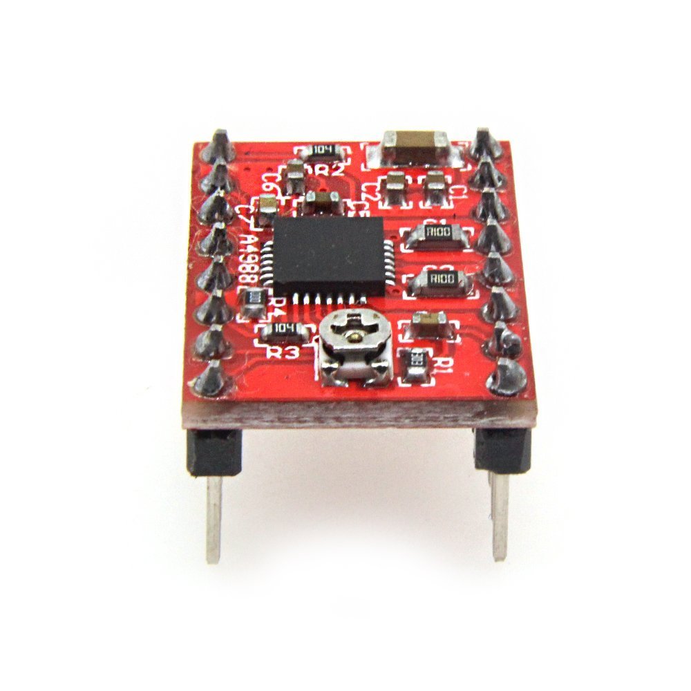
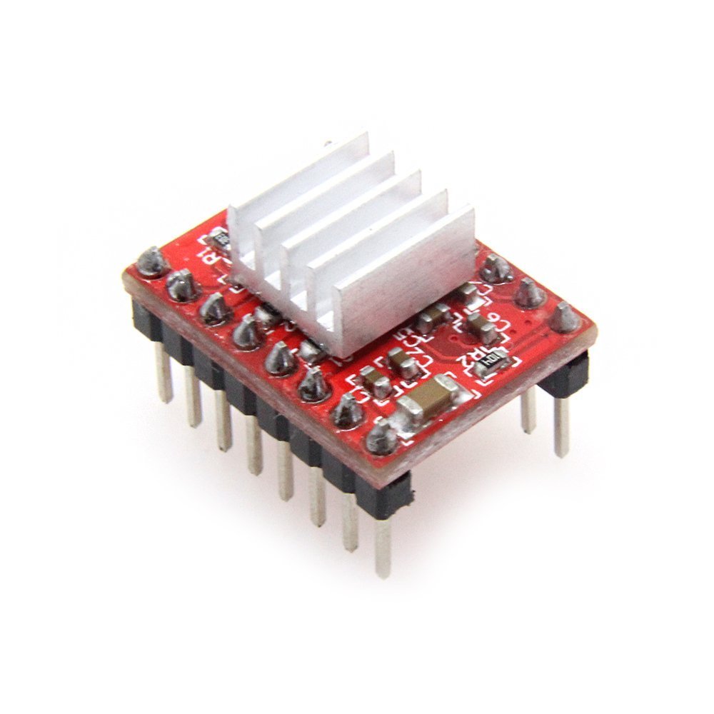
Take precise control of your bipolar stepper motors with this A4988 Microstepping Driver Module — a compact, powerful breakout board built on Allegro's A4988 DMOS driver IC. Pololu and StepStick compatible, it drops right into RAMPS 1.4 boards, CNC shields, and custom Arduino projects with zero modification. A heatsink is included in every package for reliable, high-current operation right out of the box.
⚡ Why Choose This Driver?
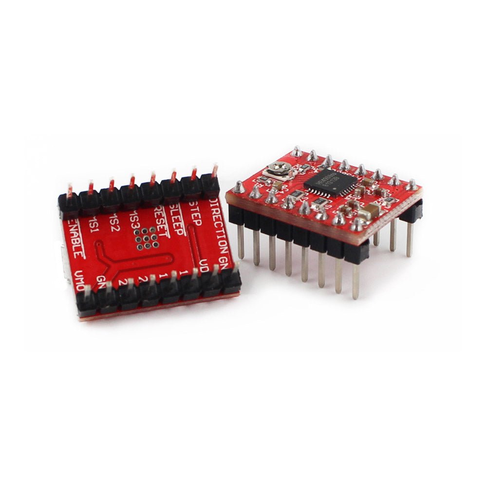
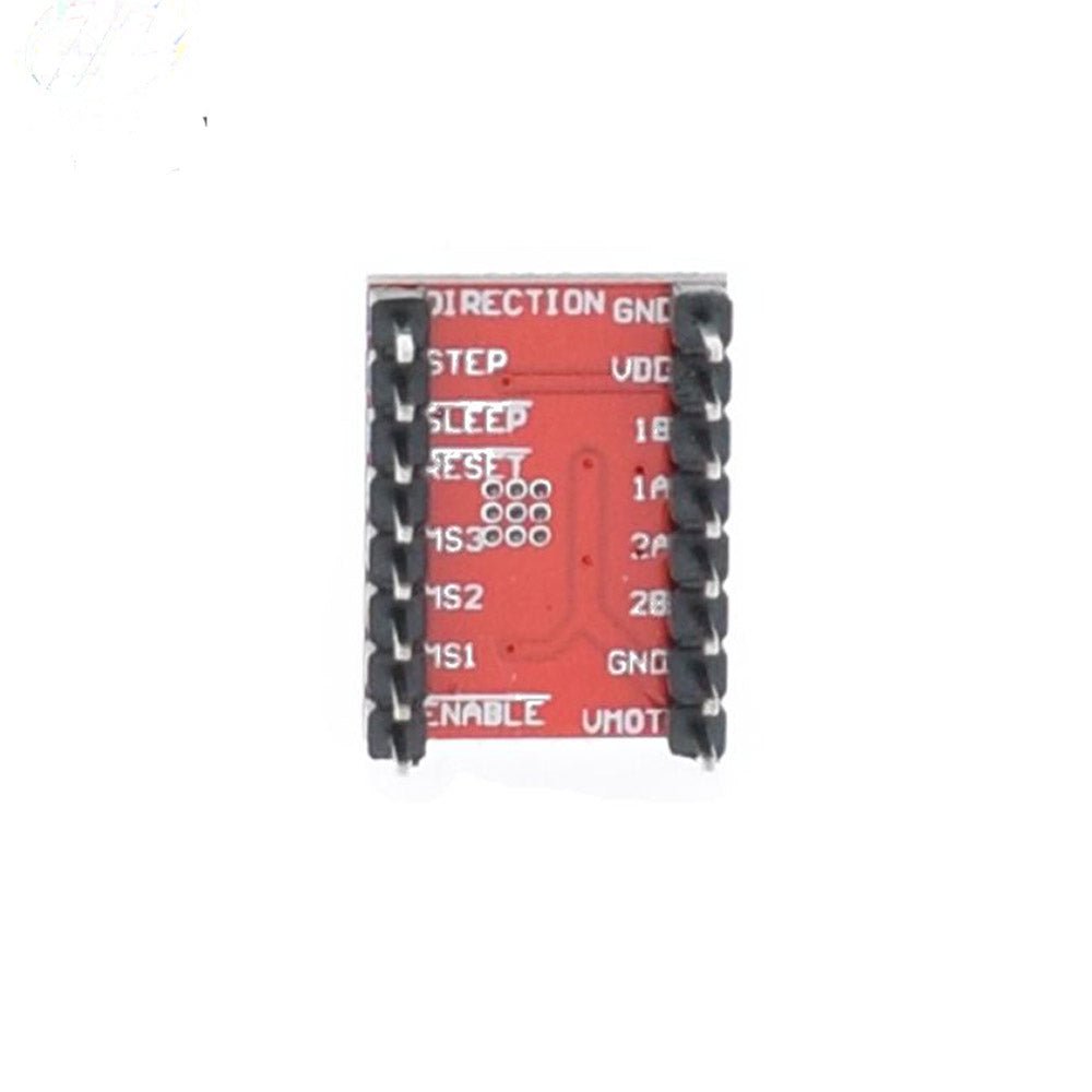
- Simple 2-pin control — Just STEP and DIR pins from your microcontroller. No complex phase-sequence tables or high-frequency control lines to program.
- 5 microstepping resolutions — Full-step, 1/2, 1/4, 1/8, and 1/16 step for smooth, quiet, precision motion.
- Adjustable current limiting — Onboard potentiometer lets you set the exact current for your motor, protecting it from overheating and missed steps.
- Built-in protection — Thermal shutdown, overcurrent protection, ground fault protection, and load short-circuit protection keep your driver and motor safe.
- Wide voltage range — Operates from 8V to 35V motor supply with 3V–5.5V logic levels, compatible with both 3.3V and 5V microcontrollers.
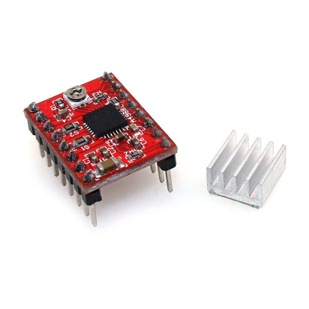
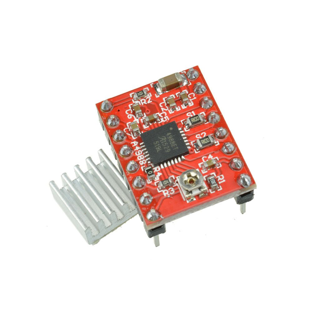
- Heatsink included — Achieve up to 2A per phase with the included heatsink attached; 1A continuous without additional cooling.
🔧 Perfect For
- 3D Printers — Drop-in replacement for RAMPS 1.4 and other RepRap electronics (Pololu/StepStick footprint).
- CNC Machines — Drive NEMA 17 and smaller NEMA 23 stepper motors for routers, laser cutters, and engravers.
- Robotics — Precise positioning for robotic arms, pan-tilt mechanisms, and automated platforms.
- Arduino & IoT Projects — Pairs seamlessly with Arduino Uno, Mega, Nano, ESP32, and other popular microcontrollers.
- Camera Sliders & Turntables — Smooth, vibration-free motion for photography and videography rigs.
🛠️ How It Works
The A4988's built-in translator is the key to its simplicity. Each pulse on the STEP pin advances the motor by one microstep. The DIR pin sets rotation direction. Three pins (MS1, MS2, MS3) select the microstepping resolution — tie them low for full-step or set them high in various combinations for up to 1/16 microstepping. That's it — no lookup tables, no complex timing, no dedicated motor controller needed.
Microstepping Resolution Table
| MS1 | MS2 | MS3 | Resolution |
|---|---|---|---|
| Low | Low | Low | Full Step |
| High | Low | Low | 1/2 Step |
| Low | High | Low | 1/4 Step |
| High | High | Low | 1/8 Step |
| High | High | High | 1/16 Step |
Setting the Current Limit (VREF)
Before powering your motor, use the onboard potentiometer to set the current limit. Measure the voltage at the VREF test point with a multimeter and use this formula:
Current Limit = VREF × 2.5
For example, to set a 1A limit, adjust the potentiometer until VREF reads 0.4V. This protects your motor from overheating and ensures optimal torque.
📐 Specifications
- Driver IC: Allegro A4988 DMOS Microstepping Driver
- Motor supply voltage: 8V – 35V
- Logic voltage: 3V – 5.5V
- Continuous current per phase: 1A (no heatsink)
- Maximum current per phase: 2A (with heatsink / active cooling)
- Microstep resolutions: Full, 1/2, 1/4, 1/8, 1/16
- Control interface: STEP / DIR (2-pin minimum)
- Current adjustment: Onboard potentiometer (VREF)
- Protection features: Thermal shutdown, overcurrent, ground fault, load short-circuit
- Compatibility: Pololu / StepStick footprint, RAMPS 1.4, CNC Shield V3
- Board dimensions: ~20mm × 15mm
📦 Package Contents
- 1 × A4988 Stepper Motor Driver Module
- 1 × Adhesive Heatsink
📄 Documentation & Resources
Share

Works and got me through my senior design project
If you are needing to drive a NEMA 17 motor up to 1 or maybe 2 Amps this driver module may be just what you need. I have seen a lot of reviews that mention module overheating and motors that just vibrate or run erratically when connected to the module and I have to say the same thing happened to me. It wasn’t the driver module’s fault though. I found that if you crank the reference voltage potentiometer fully counterclockwise before ever connecting power and then easing it up clockwise incrementally once power is applied and monitoring the stepper motor coil amperage you will avoid the overheating issue. The buzzing motor, or erratic operation issue occurs if you don’t connect the motor windings up to the driver outputs 1A, 1B, 2A, and 2B correctly. StepperOnline labels the windings as A+, A-, B+, and B-. If you connect A+ to 1A, A- to 1B, B+ to 2A, and B- to 2B things work as you would expect. Once I figured this out I was able to drive the motor to 0.6A under full load (stalled motor armature) for several minutes with no signs of overheating in the driver module or the stepper motor. My power supply could only drive 12 volts at 0.6A so I couldn’t push things any higher but since things stayed cool and stable at those levels (except for my power supply!) I am pretty confident that when my new power supply comes in I will still be OK at 1.5 to 2 amps. Will come back and edit this review if I find out otherwise. At this point though, I am very satisfied with the A4988 stepper motor driver! One other note - one of the two tantalum capacitors I had in parallel across the motor supply power connectors in the photo exploded like a firecracker during this testing. And, no, I didn’t have the polarity wrong on the one that exploded. They were both rated at 33uF and 35 volts. Switched to a 2200uF 50v electrolytic and it help up just fine. Guessing that transients generated by the motor windings exceeded the voltage rating and caused the poor little bugger to short out and over heat.
I was given a 3D printer that did not work correctly. The filament was not advancing. I replaced the stepper driver with this one, and it started working.
Exactly what I needed! Worked perfectly. Love that it’s a 2 pack so I have a backup on hand in case any other issues arise unexpectedly.