


KY-040 Rotary Encoder Module with Pushbutton Switch for Arduino, Raspberry Pi, ESP32
KY-040 Rotary Encoder Module with Pushbutton Switch for Arduino, Raspberry Pi, ESP32
Couldn't load pickup availability
📋 Overview
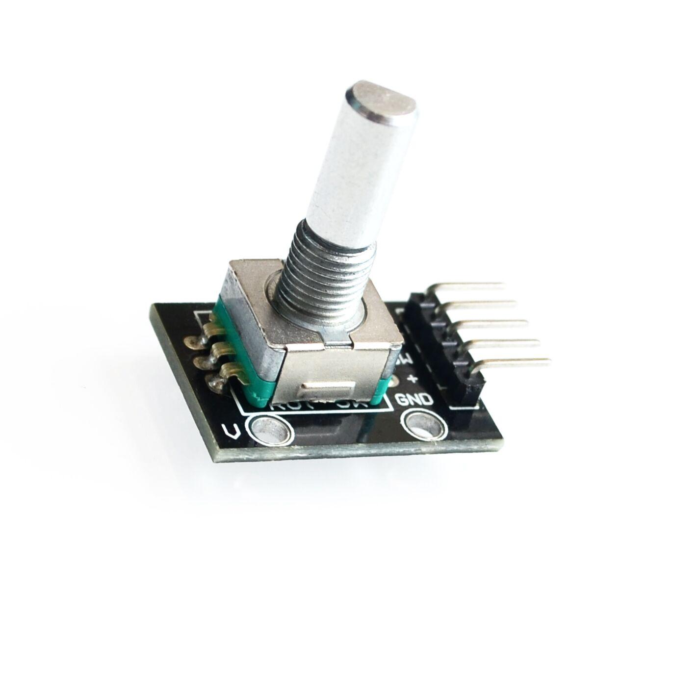
The KY-040 Rotary Encoder Module is a 360-degree rotary input device — a control knob — that tells your microcontroller how much the knob has been rotated and which direction it's turning. Unlike a potentiometer, a rotary encoder has no start or end point; it spins continuously in either direction, outputting digital pulses your code can count.
The module also includes a built-in pushbutton switch activated by pressing down on the shaft — perfect for confirming menu selections, toggling modes, or adding a second input without extra components. With on-board 10kΩ pull-up resistors on all signal lines, you can connect it directly to your microcontroller with just jumper wires — no breadboard resistors needed.
⭐ Key Features
- Continuous 360° Rotation — No mechanical stops; spins freely in both directions
- 20 Detents Per Revolution — Tactile clicks at every 18° for precise step-by-step input
- Quadrature Output (CLK + DT) — Two-channel output for reliable direction detection
- Built-in Pushbutton Switch — Press the shaft to activate a normally-open momentary switch
- On-Board Pull-Up Resistors — 10kΩ pull-ups on CLK, DT, and SW lines included on the PCB
- 5V and 3.3V Compatible — Works with Arduino, Raspberry Pi, ESP32, STM32, and more
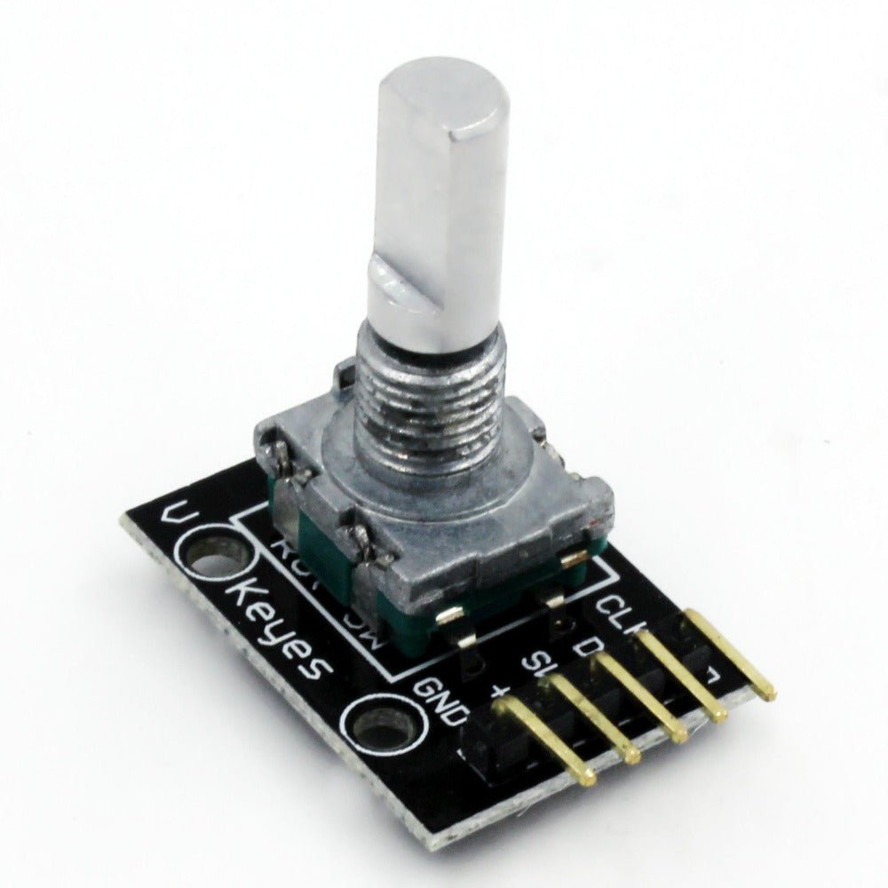
- Simple 5-Pin Interface — CLK, DT, SW, +, GND — connect with standard jumper wires
📊 Specifications
| Encoder Type | Incremental rotary encoder |
| Operating Voltage | 5V DC (also works with 3.3V) |
| Detents Per Revolution | 20 (18° per detent) |
| Pulses Per Revolution | 20 |
| Rotation | Continuous 360° (no mechanical stops) |
| Pushbutton Switch | Normally open, momentary (active LOW) |
| On-Board Pull-Up Resistors | 10kΩ on CLK, DT, and SW |
| Output Signal | 2-bit quadrature (Gray code) |
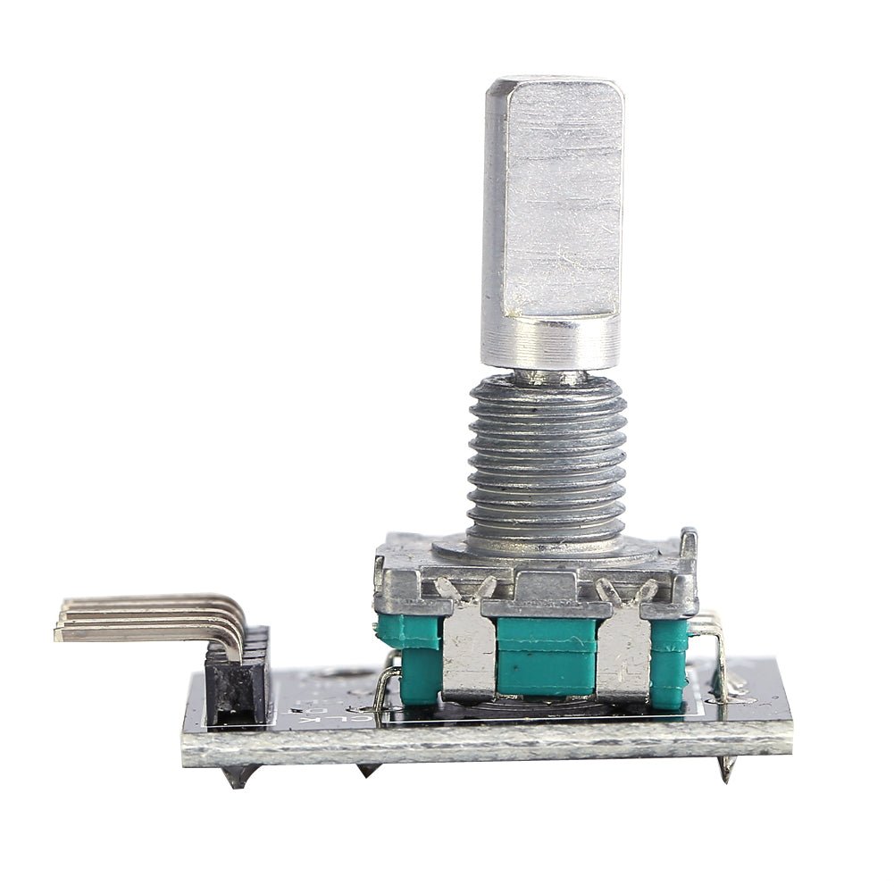
| Module Dimensions | Approx. 30 × 18 × 30 mm (1.18 x 0.71 x 1.18 inches) L × W × H |
📦 What's in the Box
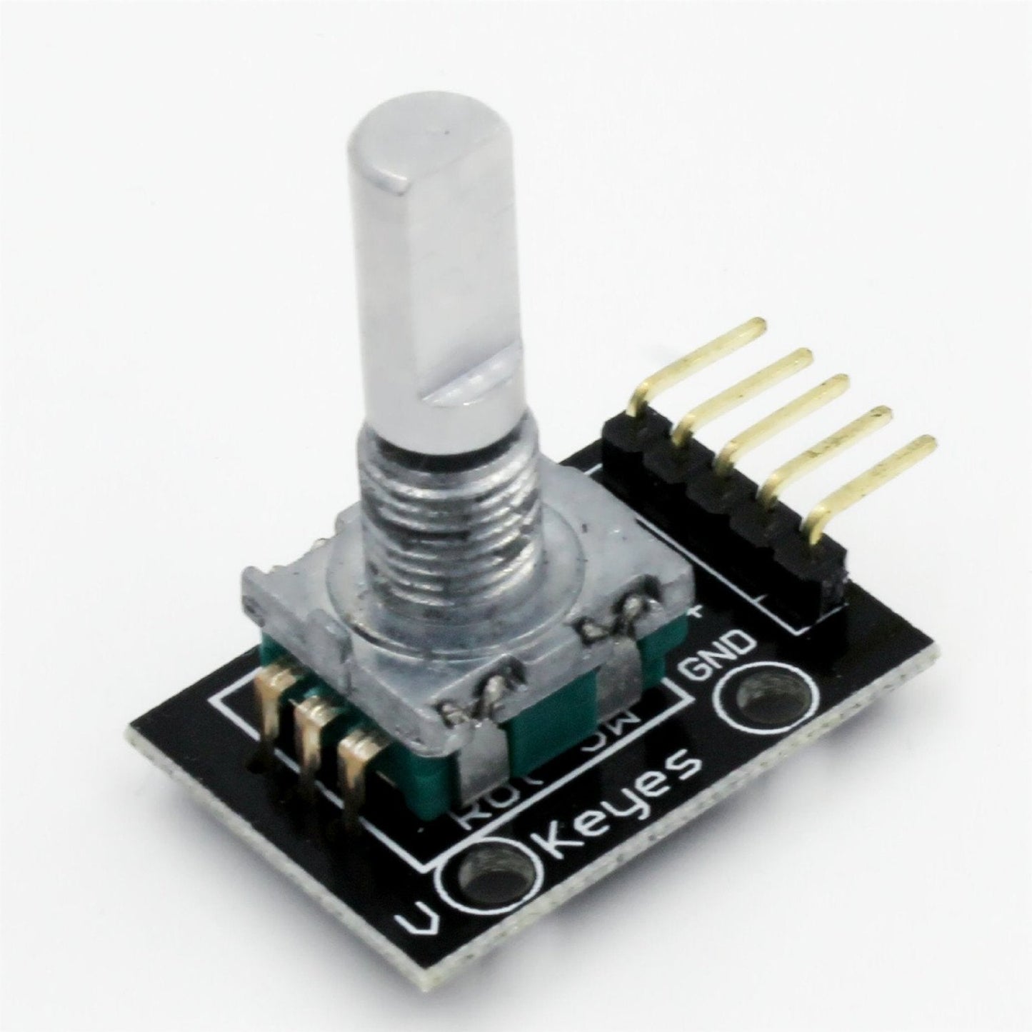
- 1x KY-040 Rotary Encoder Module (with knob shaft)
Jumper wires, Arduino board, and knob cap are not included. Any standard 6mm D-shaft knob will fit.
🔌 Compatible With
- Arduino (Uno, Mega, Nano, Leonardo, Due, and compatibles)
- Raspberry Pi (all models — use 3.3V logic)
- ESP32 / ESP8266
- STM32, Teensy, and other 3.3V–5V microcontrollers
- PIC and AVR microcontrollers
🚀 Getting Started
- Connect CLK → Pin 2, DT → Pin 3, SW → Pin 4, + → 5V, GND → GND on your Arduino
- Open the Arduino IDE and paste the example sketch from the User Guide
- Upload the sketch and open the Serial Monitor at 9600 baud
- Turn the encoder knob — the Serial Monitor displays direction and position count
- Press the shaft down — the Serial Monitor displays "Button pressed!"
💡 Tip: See our complete User Guide linked below for detailed wiring diagrams, pinout tables, sample code, and troubleshooting tips.
📌 Pinout
| Pin | Function |
|---|---|
| CLK | Encoder Output A (clock signal) |
| DT | Encoder Output B (direction signal) |
| SW | Pushbutton switch output (active LOW when pressed) |
| + | Power supply (+5V DC) |
| GND | Ground |
🎯 Typical Applications
- Menu navigation and selection on LCD/OLED displays
- Volume and brightness controls
- Parameter adjustment (set points, thresholds, timer values)
- Stepper and servo motor speed/direction control
- Scrolling through lists or data
- CNC and 3D printer manual jog controls
- DIY audio equipment (amplifiers, mixers)
- Robotics — steering and configuration input
⚠️ Important Notes
- Mechanical encoders produce contact bounce — use software debouncing or add 100nF capacitors between CLK/GND and DT/GND for clean signals
- For best responsiveness, connect CLK and DT to interrupt-capable pins (Pins 2 and 3 on Arduino Uno)
- Keep jumper wires under 20cm (8 inches) to minimize electrical noise
- The module includes pull-up resistors — you generally do not need to enable Arduino's internal pull-ups for CLK and DT
📄 Documentation & Resources
- KY-040 Rotary Encoder Module User Guide — Wiring diagrams, pinout, example code, and troubleshooting
- All Sensor, Detector and Input Module User Guides
Sold and supported by Envistia Mall. Ships from the USA. For wiring diagrams, sample code, and troubleshooting, see the User Guide. The manufacturer and Envistia LLC (dba Envistia Mall) are not responsible for any damages or losses resulting from the use of this product. Always follow proper electrical safety practices when working with electronic components. Specifications are based on manufacturer data and are subject to change without notice.
Share