


Controlador de controlador de motor paso a paso de impresora 3D A4988 con placa de expansión
Controlador de controlador de motor paso a paso de impresora 3D A4988 con placa de expansión
No se pudo cargar la disponibilidad de retiro
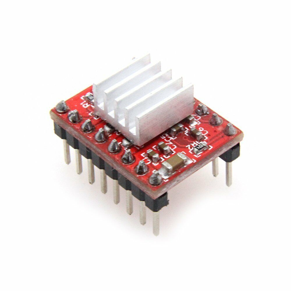
Esta placa de expansión incluye un controlador de motor paso a paso A4988 que permite una conexión sencilla a su Ardiuno u otro microcontrolador y motores paso a paso.
Los puentes 1-3 corresponden a las configuraciones MS1, MS2 y MS3 del A4988 para controlar las resoluciones de paso.
El conector JST Jm está conectado a los motores, los pines 1-4 corresponden a 1B, 1A, 2A y 2B, respectivamente.
Jv es la fuente de alimentación de apoyo, conectada a una fuente de alimentación de 5V y 9V-24V.
ESDG de Jc correspondiente respectivamente a la salida de señal de la unidad EnableStepDirGnd conectada.
Especificaciones de la placa de expansión:
- Color: Rojo
- Tamaño: aprox. 43 x 35 x 10 mm
Especificaciones de la placa A4988:
- Tensión mínima de funcionamiento: 8 V
- Tensión máxima de funcionamiento: 35 V
- Corriente continua por fase: 1A
- Corriente máxima por fase: 2A (con refrigeración)
- Tensión lógica mínima: 3V
- Voltaje lógico máximo: 5,5 V
- Circuito de apagado térmico
- Protección contra fallas a tierra
- Protección contra cortocircuitos de carga
- Resoluciones de micropasos: completa, 1/2, 1/4, 1/8 y 1/16
Contenido del paquete:
1 placa de expansión A4988
1 módulo de controlador de motor paso a paso A4988
1 disipador de calor A4988
Instrucciones de programación y funcionamiento impresas
¡Consíguelo más rápido! Enviamos en 1 día hábil desde nuestra oficina en Colorado para una entrega rápida.
Share


Works and got me through my senior design project
If you are needing to drive a NEMA 17 motor up to 1 or maybe 2 Amps this driver module may be just what you need. I have seen a lot of reviews that mention module overheating and motors that just vibrate or run erratically when connected to the module and I have to say the same thing happened to me. It wasn’t the driver module’s fault though. I found that if you crank the reference voltage potentiometer fully counterclockwise before ever connecting power and then easing it up clockwise incrementally once power is applied and monitoring the stepper motor coil amperage you will avoid the overheating issue. The buzzing motor, or erratic operation issue occurs if you don’t connect the motor windings up to the driver outputs 1A, 1B, 2A, and 2B correctly. StepperOnline labels the windings as A+, A-, B+, and B-. If you connect A+ to 1A, A- to 1B, B+ to 2A, and B- to 2B things work as you would expect. Once I figured this out I was able to drive the motor to 0.6A under full load (stalled motor armature) for several minutes with no signs of overheating in the driver module or the stepper motor. My power supply could only drive 12 volts at 0.6A so I couldn’t push things any higher but since things stayed cool and stable at those levels (except for my power supply!) I am pretty confident that when my new power supply comes in I will still be OK at 1.5 to 2 amps. Will come back and edit this review if I find out otherwise. At this point though, I am very satisfied with the A4988 stepper motor driver! One other note - one of the two tantalum capacitors I had in parallel across the motor supply power connectors in the photo exploded like a firecracker during this testing. And, no, I didn’t have the polarity wrong on the one that exploded. They were both rated at 33uF and 35 volts. Switched to a 2200uF 50v electrolytic and it help up just fine. Guessing that transients generated by the motor windings exceeded the voltage rating and caused the poor little bugger to short out and over heat.
I was given a 3D printer that did not work correctly. The filament was not advancing. I replaced the stepper driver with this one, and it started working.
Exactly what I needed! Worked perfectly. Love that it’s a 2 pack so I have a backup on hand in case any other issues arise unexpectedly.