XL4015 5A DC-DC Step-Down CC/CV Buck Converter with Volt, Amp & Power Meter — Adjustable 1.2V-34V Out 8V-36V In Battery Charger & LED Driver with USB Output
XL4015 5A DC-DC Step-Down CC/CV Buck Converter with Volt, Amp & Power Meter — Adjustable 1.2V-34V Out 8V-36V In Battery Charger & LED Driver with USB Output
Couldn't load pickup availability
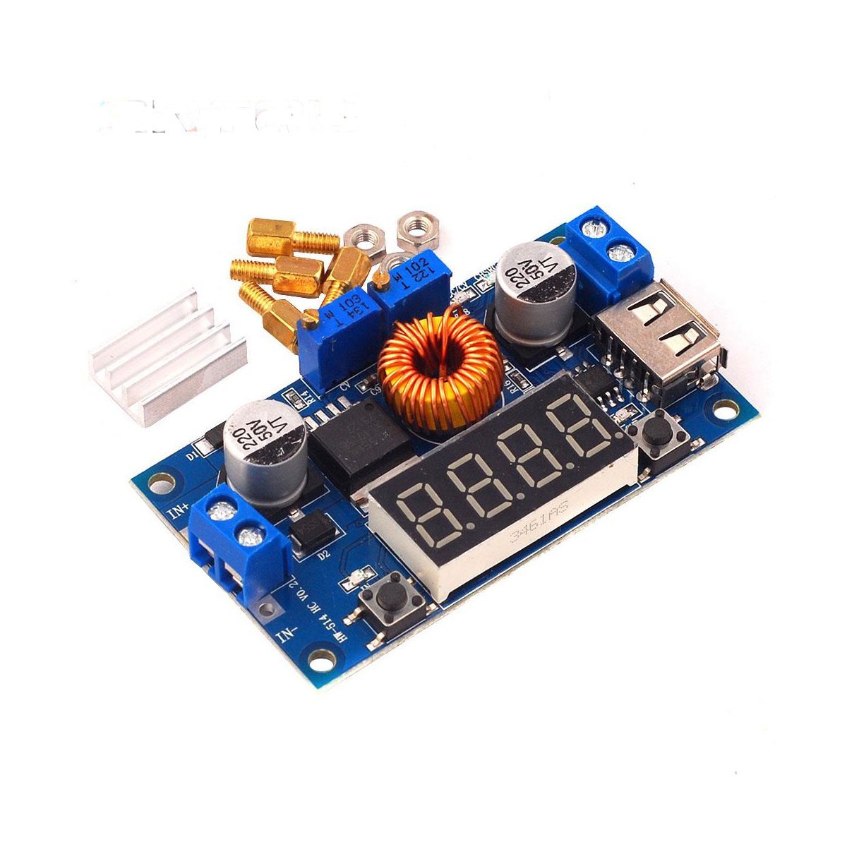
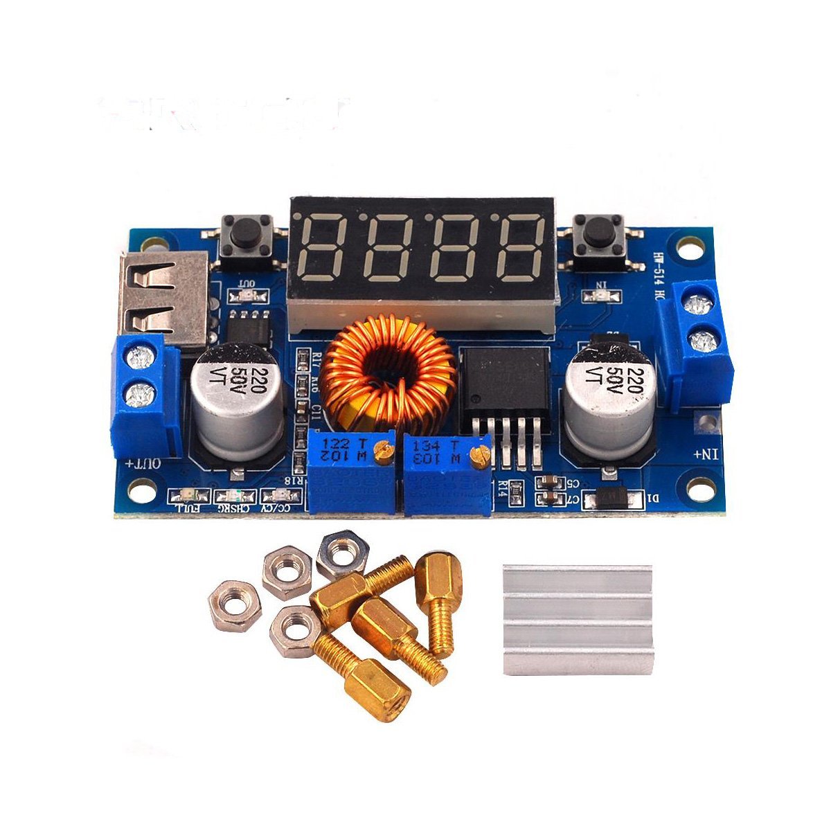
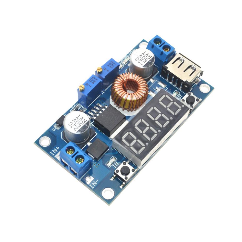
More than just a voltage regulator — this XL4015 5A CC/CV Step-Down Buck Converter is a complete adjustable power module with Constant Voltage, Constant Current control, a built-in LED display showing real-time voltage, current, and power, and both screw terminal and USB outputs. Whether you're charging batteries, driving high-power LEDs, building a bench power supply, or regulating solar panel output, this module does it all — and shows you exactly what it's doing on the display.
⚡ Why Choose This Module?
- Dual CC/CV control — Two onboard potentiometers let you independently set the output voltage (1.2V–34V) and current limit (0–5A). The module automatically switches between Constant Voltage and Constant Current modes based on load demand.
- Built-in LED meter — No external multimeter needed. The onboard display cycles through input voltage, output voltage, output current, and output power at the press of a button.
- Dual output connections — Screw terminals for general wiring plus a USB Type-A port for charging phones, powering Raspberry Pi, or any USB device (when set to 5V).
- High efficiency — Up to 96% conversion efficiency at 180 KHz switching frequency means less wasted energy and less heat compared to linear regulators.
- Wide voltage range — Accepts 8V–36V input and outputs 1.2V–34V, covering virtually any DC step-down application.
- Built-in protection — Over-temperature, over-current, short-circuit, and reverse polarity (input) protection keep your module and connected devices safe.
🔧 How CC/CV Works
This module has two operating modes that work together automatically:
- Constant Voltage (CV) mode: The module maintains your set output voltage regardless of load. This is normal operation — like a standard power supply.
- Constant Current (CC) mode: When the load tries to draw more current than your set limit, the module automatically reduces voltage to maintain a steady current. This is essential for safely charging batteries and driving LEDs.
Example — Charging a Li-ion battery: Set CV to 4.2V and CC to 1A. The module starts in CC mode, pushing a steady 1A while voltage rises. When the battery reaches 4.2V, it transitions to CV mode, holding voltage while current tapers off. This is exactly the CC/CV charging profile that lithium batteries require.
🎯 Perfect For
- Battery charging — Li-ion, LiFePO4, lead-acid, and NiMH batteries with proper CC/CV profiles. Set the exact voltage and current for your chemistry.
- LED & laser diode driving — Constant current mode delivers steady, flicker-free current to high-power LEDs and laser diodes regardless of temperature drift.
- DIY bench power supply — Adjustable voltage and current with a built-in display — add a case and binding posts for a fully functional bench supply.
- USB charging station — Set to 5V and use the onboard USB port to charge phones, tablets, or power Raspberry Pi and Arduino projects.
- Solar panel regulation — Stabilize fluctuating solar panel output to a steady voltage for battery charging or direct device power.
- Automotive & marine projects — Step down 12V/24V vehicle power to 5V, 9V, or any voltage your devices need.
- STEM education — The built-in display makes it an excellent teaching tool for demonstrating voltage regulation, current limiting, and power conversion concepts.
📡 LED Display Modes
Press the onboard button to cycle through four display modes:
| Press | Display | What It Shows |
|---|---|---|
| 1 | Input Voltage (V) | Voltage at the input terminals from your power supply |
| 2 | Output Voltage (V) | Voltage at the output terminals / USB port |
| 3 | Output Current (A) | Current being drawn by your load right now |
| 4 | Output Power (W) | Power delivered to your load (V × A) |
📐 Specifications
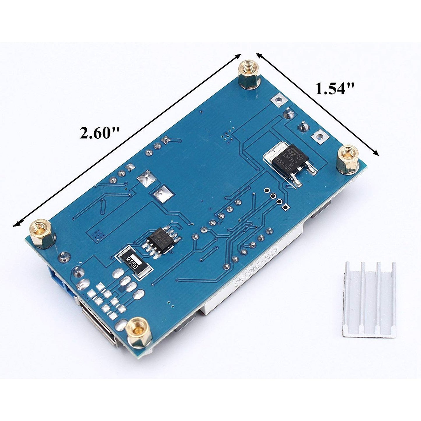
- Converter IC: XL4015
- Type: DC-DC Buck (Step-Down)
- Input voltage: 8V – 36V DC
- Output voltage: 1.2V – 34V DC (adjustable)
- Output current: 0 – 5A peak / 4A continuous recommended
- Minimum dropout: ~1.5V (input must be ≥1.5V above output)
- Conversion efficiency: Up to 96%
- Switching frequency: 180 KHz
- Control modes: Constant Voltage (CV) / Constant Current (CC)
- Adjustment: Two multi-turn potentiometers (CV-ADJ and CC-ADJ)
- Display: LED digital meter (V, A, W, input V) with push-button mode select
- Output connections: Screw terminals + USB Type-A port
- Input connections: Screw terminals (IN+ / IN−)
- Protections: Over-temperature, over-current, short-circuit, reverse polarity (input)
- Operating temperature: −40°C to +85°C
- Board dimensions: ~65mm × 40mm × 20mm
📦 Package Contents
- 1 × XL4015 5A CC/CV Step-Down Buck Converter Module with LED Display
DC power supply, battery, load, and wiring are not included.
📄 Documentation & Resources
Share