


2-Channel 5V PWM Pulse / Square Wave Generator Module 1Hz-150KHz Frequency
2-Channel 5V PWM Pulse / Square Wave Generator Module 1Hz-150KHz Frequency
Couldn't load pickup availability
📋 Overview
This economical 2-Channel 5V PWM Pulse / Square Wave Generator Module gives you two fully independent square wave outputs, each with its own adjustable frequency and duty cycle. A simple 3-button interface and 3-digit LED display make it easy to dial in exactly the signal you need — no computer or microcontroller required. When automation is needed, the built-in RS-232 serial interface lets you control both channels programmatically at 9600 baud.
With a frequency range spanning 1Hz to 150KHz and duty cycle adjustable from 1% to 100% in 1% steps, this module is equally at home on the workbench as a signal generator or built into a project as a permanent PWM source. Power it from any MicroUSB charger or supply up to 30V through the onboard pads.
Note: This module is produced by more than one manufacturer and may arrive with one of two firmware versions. Both versions cover the same frequency range and specifications — only the button operation steps differ. Complete instructions for both versions are provided in the User Guide.
⭐ Key Features
- Two fully independent PWM channels — set different frequencies and duty cycles on each
- Wide frequency range: 1Hz to 150KHz
- Adjustable duty cycle: 1% to 100% in 1% increments
- Intuitive 3-button control (SET, UP, DOWN) with 3-digit LED display
- RS-232 serial interface for computer or microcontroller control (9600 bps, 8N1)
- MicroUSB 5V power input — power from any USB charger or power bank
- Wide supply range: 5V to 30V via onboard pads
- Up to 30mA output current per channel
- Output voltage adjustable via external supply (requires one-time trace cut)
- Settings saved to memory — module powers up with last-used frequency and duty cycle
- Operating temperature: −30°C to 70°C
📦 What's in the Box
- 1× 2-Channel 5V PWM Pulse / Square Wave Generator Module
Note: Connecting wires are not included. Output signal connections require soldering directly to the pads on the board.
📊 Specifications
| Parameter | Value |
|---|---|
| Number of Channels | 2 (fully independent) |
| Supply Voltage | 5V – 30V DC (MicroUSB or VCC/GND pads) |
| Frequency Range | 1Hz – 150KHz |
| Frequency Precision | ±2% |
| Duty Cycle Range | 1% – 100% (1% steps) |
| Output Voltage (default) | Equals supply voltage (nominally 5V peak-to-peak from USB) |
| Output Voltage (adjustable) | 5V – 30V with external supply and PCB trace cut |
| Max Output Current | 30mA per channel |
| Control Interface | SET / UP / DOWN buttons + 3-digit LED display |
| Serial Interface | RS-232, 9600 bps, 8 data bits, 1 stop bit, no parity, no flow control |
| Power Input | MicroUSB (5V) or VCC/GND solder pads |
| Operating Temperature | −30°C to 70°C |
| Dimensions | [Ron — please add dimensions: Approx. XX × YY × ZZ mm (A.A × B.B × C.C inches) L × W × H] |
| Part Number | EM-OTHER-0010 |
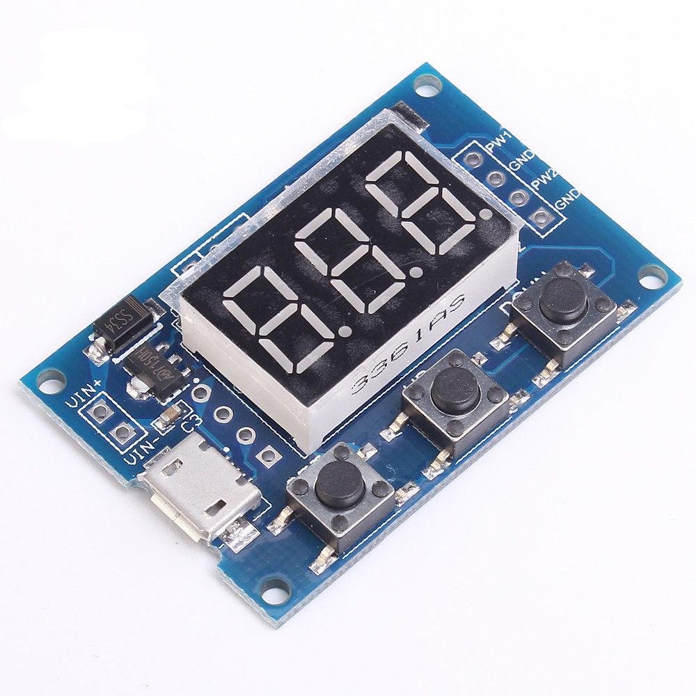
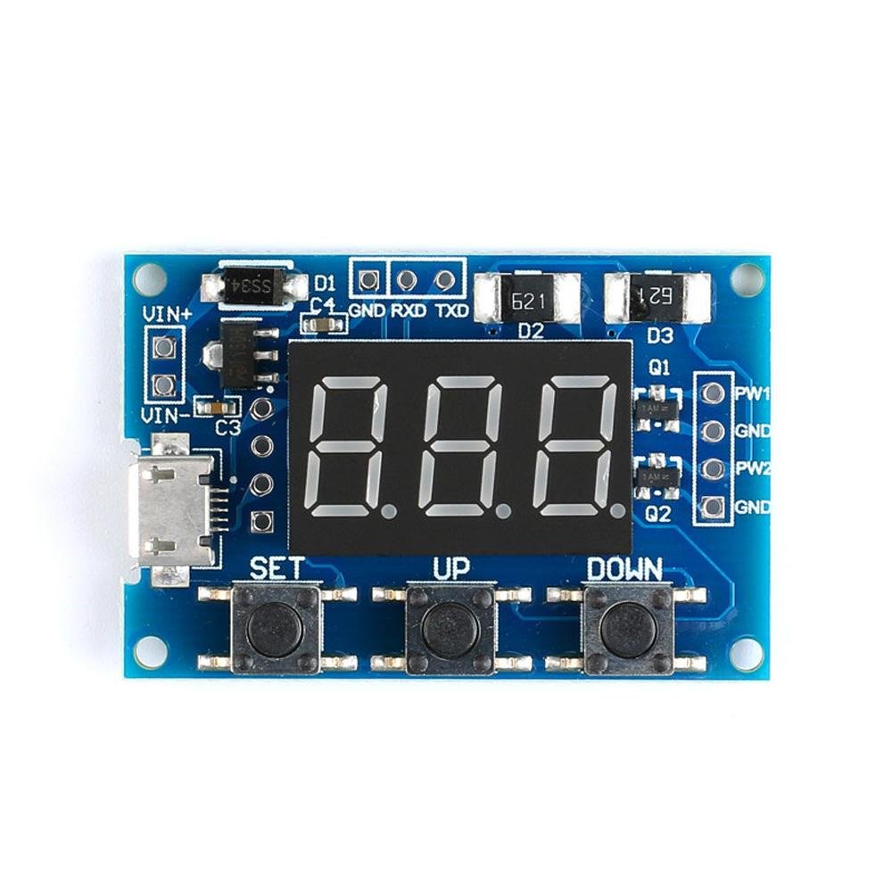
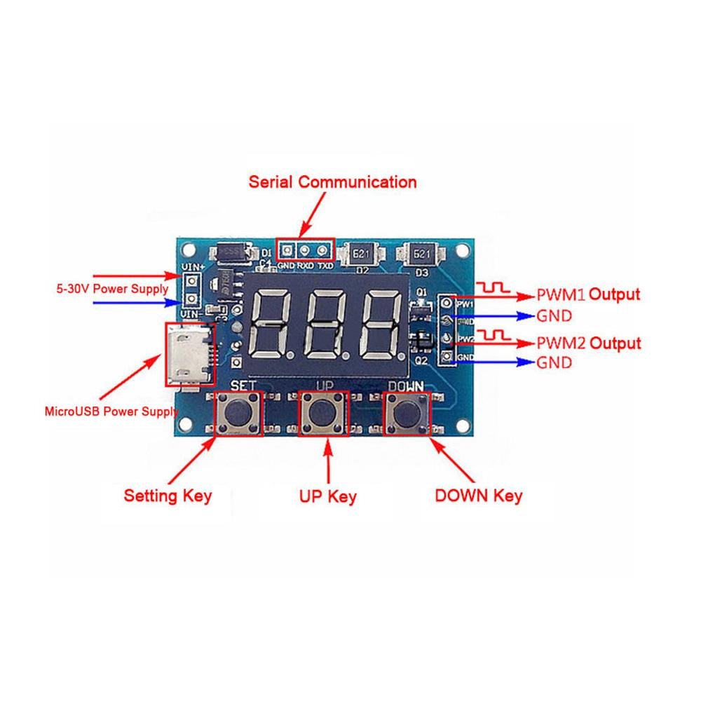
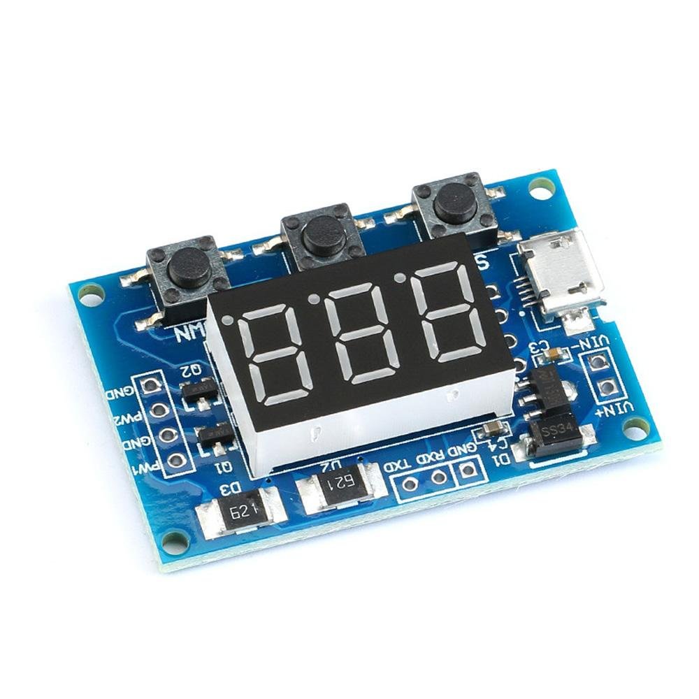
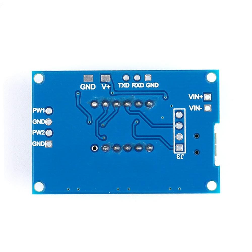
📌 Connections & Pinout
All signal and power connections are made via solder pads on the board. The MicroUSB port is the simplest way to power the module at 5V. VCC and GND pads allow an alternative DC supply from 5V to 30V.
| Connection | Type | Description |
|---|---|---|
| MicroUSB | Power input | 5V power — connect to any USB charger, power bank, or computer port |
| VCC | Power pad | DC positive supply, 5V – 30V. Alternative to MicroUSB. |
| GND | Ground pad | Common ground — share with the ground of your connected circuit |
| CH1 / OUT1 | Signal output pad | PWM Channel 1 square wave output |
| CH2 / OUT2 | Signal output pad | PWM Channel 2 square wave output |
| Back-side pads | External voltage input | Used to set output signal voltage independently (see Important Notes) |
🔧 Button Operation
The module has three buttons — SET, UP, and DOWN — and a 3-digit LED display. Short-pressing SET cycles through the four parameters: Channel 1 Frequency, Channel 1 Duty Cycle, Channel 2 Frequency, and Channel 2 Duty Cycle. Once a parameter is selected, UP and DOWN adjust its value.
Frequency is displayed and entered in one of three ranges, selected by pressing SET while in a frequency parameter. The display format indicates the active range:
| Display Format | Frequency Range | Example |
|---|---|---|
| XXX (no decimal) | 1Hz – 999Hz | 050 = 50Hz |
| XX.X or X.XX | 100Hz – 99.9KHz | 01.2 = 1.2KHz |
| X.X.X. or XXX. | 1KHz – 150KHz | 1.0.0. = 100KHz |
Two firmware versions: The exact button sequence differs slightly between the two versions of firmware shipped with this module. The specifications and frequency range are identical. Full step-by-step instructions for both versions are in the User Guide — see the Documentation & Resources section below.
💻 RS-232 Serial Control
Both channels can be controlled via RS-232 serial commands. Connect a serial adapter or microcontroller UART to the module's serial pads at 9600 baud, 8N1, no flow control.
| Command | Description | Example |
|---|---|---|
S1FXXXT |
Set CH1 frequency in Hz (001–999) | S1F050T → 50Hz |
S1FXX.XT |
Set CH1 frequency in KHz (00.1–99.9) | S1F01.5T → 1.5KHz |
S1FX.X.X.T |
Set CH1 frequency in KHz (0.0.1.–1.5.0.) | S1F1.0.0.T → 100KHz |
S2F... |
Same formats as above for Channel 2 | S2F500T → 500Hz |
S1DXXXT |
Set CH1 duty cycle % (001–100) | S1D050T → 50% |
S2DXXXT |
Set CH2 duty cycle % (001–100) | S2D025T → 25% |
The module responds with DOWN on success and FALL if a command is not recognized or the value is out of range.
Logic Level Note: The serial interface operates at 5V logic. Use a logic level converter when connecting to 3.3V devices such as an ESP32 or Raspberry Pi.
🎯 Applications
- Stepper Motor Control: Supply step-pulse signals to A4988, DRV8825, or TMC2209 driver boards — adjust motor speed by changing output frequency
- LED and LED Strip Dimming: PWM-control brightness through a MOSFET driver stage
- Microcontroller Testing: Generate test signals for GPIO inputs during firmware development without writing any code
- Bench Signal Generator: Quick square wave source for timing circuits, relay testing, and frequency measurement verification
- Servo Motor Testing: Drive RC servos at 50Hz with variable duty cycle to test position control
- Automotive ECM Testing: Simulate RPM and vehicle speed sensor signals for bench diagnostics
- Educational Use: Demonstrate square wave generation, duty cycle, and PWM concepts in the classroom or workshop
⚠️ Important Notes
- Output signal connections require soldering — no plug-in terminals are provided for CH1, CH2, VCC, or GND pads
- Maximum output current is 30mA per channel. Use a MOSFET or transistor buffer for loads exceeding 30mA
- This module ships with one of two firmware versions; both have the same frequency range and output specifications, but button procedures differ slightly — the User Guide covers both
- Frequency precision is ±2%, suitable for PWM control and motor driving but not precision frequency reference applications
- Output voltage defaults to the supply voltage level. To use a different output voltage, an external supply must be connected to the back-side pads and the onboard trace cut — this modification is permanent
- Do not exceed 30V on either the supply input or the external output voltage pads
📄 Documentation & Resources
- User Guide — Button Operation, RS-232 Commands, Wiring & Troubleshooting
- All Logic & Timing Module User Guides
Sold and supported by Envistia Mall. Ships from the USA. For complete setup instructions, button operation procedures, RS-232 commands, and troubleshooting, visit the User Guide linked above. The manufacturer and Envistia LLC (dba Envistia Mall) are not responsible for any damages or losses resulting from the use of this product. Always follow proper electrical safety practices when working with electronic components. Specifications are based on manufacturer data and are subject to change without notice.
Share


Quality construction and works well. Fast delivery all good
The product worked but the advertised frequency is not what the product puts out. I see 100 Hz to 100kHz on my oscilloscope. Unless this product was not programmed correctly before shipping it does not work for the frequency I need which is between 47Hz to 63Hz. Can the seller update frequency output parameters so others don't buy if needing under 100Hz with a 50% duty cycle? Or can the seller provide instructions to get the frequency to adjust down to 1Hz?
Thank you for your review and feedback on our 2-Channel 5V PWM Pulse / Square Wave Generator Module. We understand your need for a lower frequency range and we would like to offer some instructions that may help you adjust the frequency to 1Hz. While you are in the frequency settings PA1 or PA2, the frequency range can be selected before entering the value by short-pressing (tapping) the SET button:
- XXX Display (Default): Frequency values from 1Hz – 999Hz frequency range
- X.XX Display (1 short press of the SET button): 10hz – 9.99Khz frequency range (i.e. 1.20 = 1.2KHz, 5.55 = 5.55KHz)
- XX.X Display (2 short presses of the SET button): 100hz – 99.9Khz frequency range (i.e. 01.2 = 1.2KHz, 55.5 = 55.5KHz)
- XXX. Display (3 short presses of the SET button): 1Khz~150Khz frequency range (i.e. 003. = 3KHz, 100. = 100KHz).
The location of the decimal point in the display indicates the range that it is set to - see the examples above.
It can also be programmed using the Serial Port RS-232 Control. Please see our support website for more detailed instructions. The URL is https://support.envistiamall.com/kb/2-channel-5v-pwm-pulse-square-wave-generator-module/
- Well Manufactured 2 Channel square wave signal generator – NO DATASHEETThe website description is accurate and this module works well for my project. Because the product is a good price and does what it says, it deserves a full 5 star rating. I was temp
Please see our online datasheet and operating instructions on our support website at https://support.envistiamall.com/kb/2-channel-5v-pwm-pulse-square-wave-generator-module/
The product works exactly as advertised. It will help jump start my "project" before I roll my own.Update: The seller does have a website with helpful information that I was unaware of when I wrote this review. No where to go up from 5 stars so my rating stays the same.I wish it had some basic documentation....specifically if I wanted to solder it down to a board for use, it would be nice to know what I am exactly connecting to ....input/output schematics without giving away the innards, if they are worried about that.Here is the pros....So its pretty accurate. Performs its stated task well. I didn't see a crystal, so I am not sure how that is.The crystal may be under the LED display....as well as the crtical "innards" making it function.Frequency and duty cycle are independently adjustable.User interface is somewhat intuitive, but you will have to figure it out by playing with the push buttons. Update: Look for sellers link to his/her website on this page.Here are the negatives.1) Zero instructions…. Update… I found them.2) No schematics....at least some interface info would help...don't want to blow it up. Still true.3) USB connector for power...ok fine. What if I hook in my own? Update: Seller has some info.4) You will need to solder to it to get signals out.....so you will need soldering skills. No biggie for me, but letting you know.5) update: you can program it through a serial interface. I haven’t tried it yet, but this is a bonus I was unaware of.Here are the unknowns.1) I didn't quantify jitter if that is important to you...you are on your own. Its not for me.2) I didn't quantify drive strength of the outputs. That is important to me, but I can always buffer the outputs. Update. I guess they can do 30mA.
Great readout and two outputsI use this for bench testing auto ECMsOne output is RPM and the other is vehicle speed