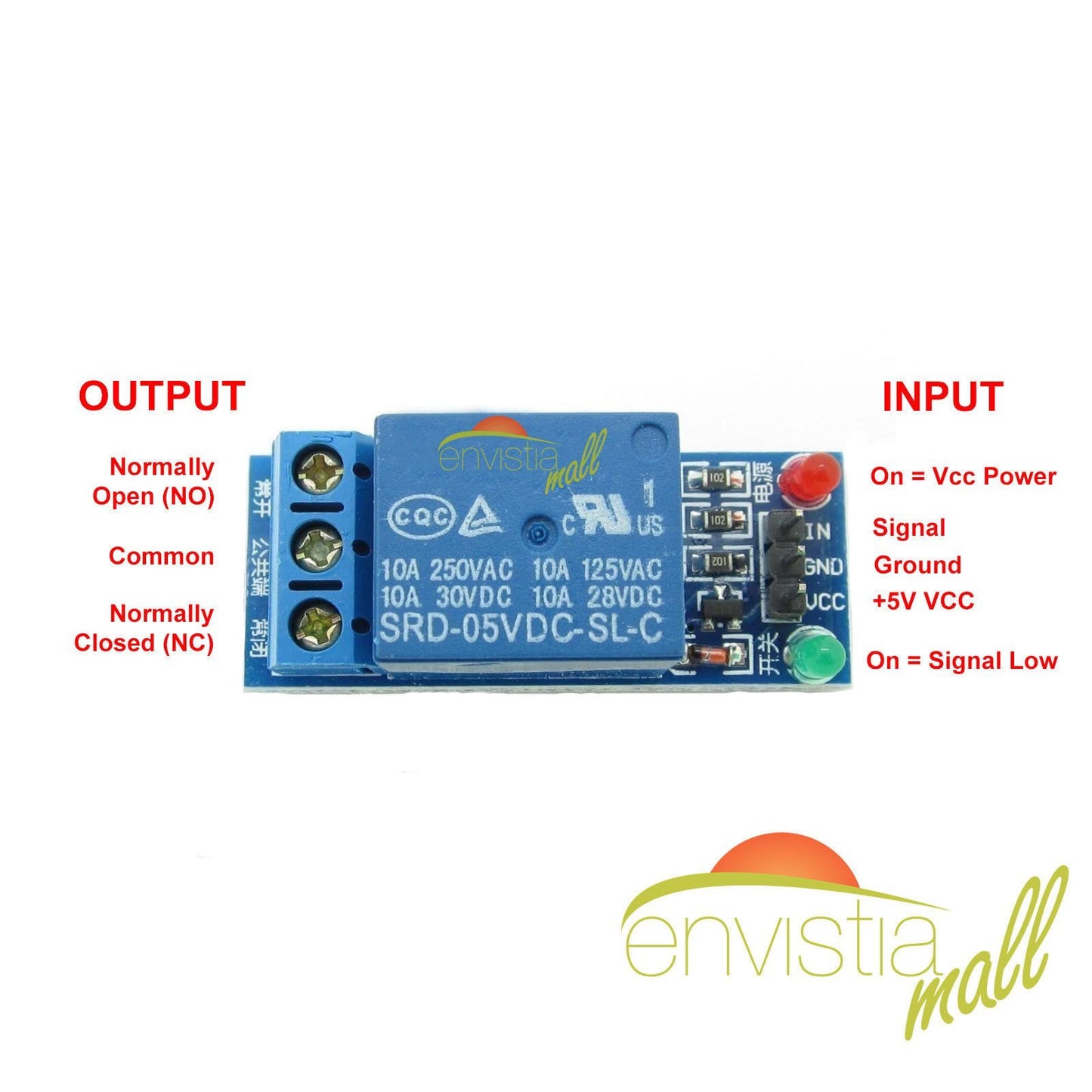
1-Channel 5V Relay Module 250V/10A
1-Channel 5V Relay Module 250V/10A
Couldn't load pickup availability
📋 Overview
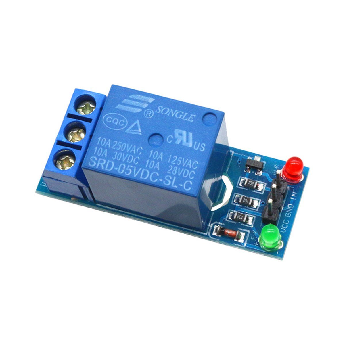
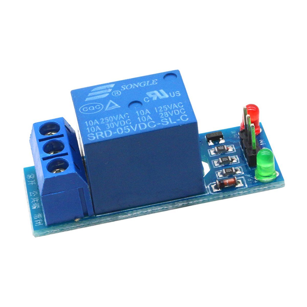
This 1-channel 5V SPDT power relay module lets you switch high-voltage AC loads — lamps, fans, heaters, motors — on and off using a simple digital signal from your microcontroller. It handles up to 10 amps at 250 VAC, making it ideal for home automation, IoT projects, and industrial control prototyping.
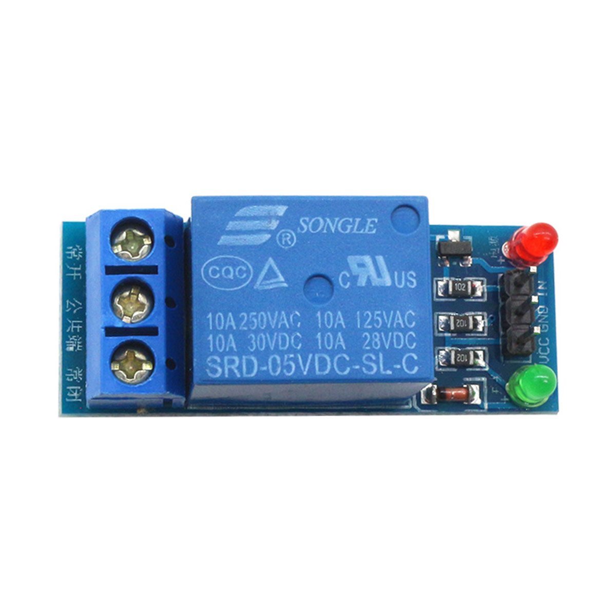
An onboard NPN transistor drives the relay coil, so your microcontroller pin only needs to provide a small control signal. A built-in flyback diode protects against voltage spikes, and dual LED indicators give you instant visual feedback — red for power, green for relay active.
⚠️ Important: This module switches high-voltage AC power (up to 250V). Improper wiring can cause electric shock, fire, or equipment damage. If you are not experienced with mains voltage wiring, consult a qualified electrician. Always disconnect power before making or changing connections.
⭐ Key Features
- 10A @ 250V AC Switching — Control lamps, fans, heaters, motors, and other AC-powered devices
- 5V Logic-Level Control — Drive directly from Arduino, Raspberry Pi, or any 5V microcontroller
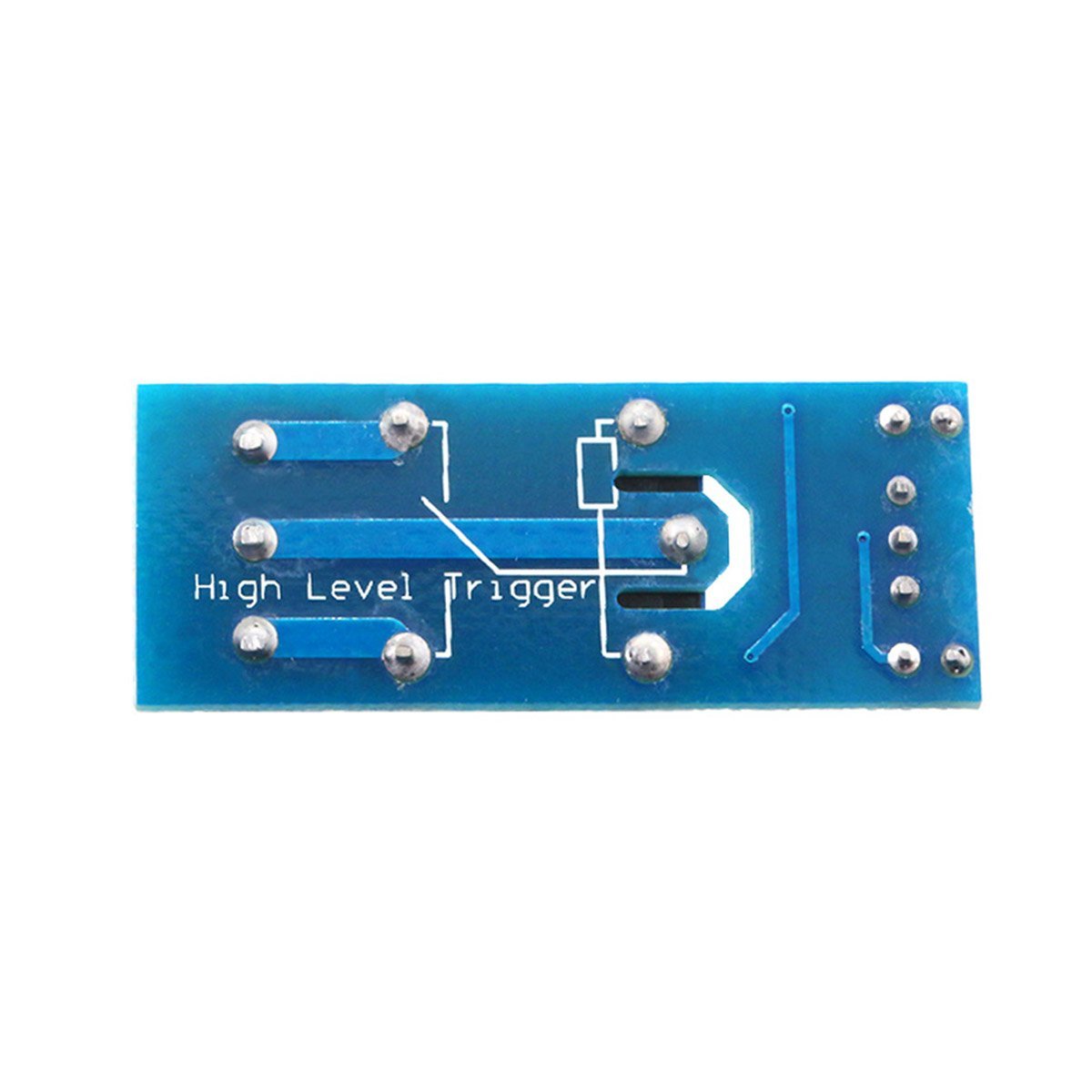
- Active Low Input — Pull the IN pin LOW to activate the relay; HIGH keeps it off
- Transistor-Driven Relay Coil — Onboard NPN transistor handles coil current so your microcontroller pin stays within safe limits
- Flyback Diode Protection — Suppresses voltage spikes when the relay coil de-energizes
- SPDT Output — Normally Open (NO) and Normally Closed (NC) terminals for flexible wiring
- Dual LED Indicators — Red LED for power, green LED for relay active status
- Screw Terminals — Secure, tool-tightened connections for high-voltage wiring
- No Library Required — Simple digital HIGH/LOW control from any microcontroller
- Compact Form Factor — Small enough for tight enclosures and breadboard-friendly projects
📊 Specifications
| Relay Type | SPDT (Single-Pole Double-Throw) |
| Number of Channels | 1 |
| Control Signal Polarity | Active Low (pull IN pin LOW to activate) |
| Max Switching Voltage | 250V AC |
| Max Switching Current | 10A AC |
| Control Voltage | 5.0V DC |
| Control Current | 20–30 mA |
| Module Operating Current | Approx. 70 mA (relay activated) |
| Drive Circuit | NPN transistor with flyback diode protection |
| Indicators | Red LED (power), Green LED (relay active) |
| Dimensions | Approx. 42 × 17 × 17 mm (1.65 × 0.67 × 0.67 inches) L × W × H |
📌 Pinout
Control Side (Low-Voltage Header)
| Pin | Function |
|---|---|
| VCC | +5V DC power input |
| GND | Ground |
| IN | Control input — LOW to activate, HIGH to deactivate |
Output Side (High-Voltage Screw Terminals)
| Terminal | Function |
|---|---|
| COM | Common — connect your power source here |
| NO | Normally Open — connected to COM when relay is activated |
| NC | Normally Closed — connected to COM when relay is off |
🚀 Getting Started
- Connect the relay module to your Arduino: VCC → 5V, GND → GND, IN → Digital Pin 7
- Upload a simple sketch that writes LOW to pin 7 to activate the relay, HIGH to deactivate
- Listen for the relay click and watch the green LED to confirm it's working
- Once verified, wire your AC load to the screw terminals (COM and NO for normally-off devices)
💡 Tip: See our complete User Guide tab for detailed wiring diagrams, pinout tables, sample code, and troubleshooting tips.
🎯 Applications
- Home automation — control lights, fans, and appliances from your microcontroller
- IoT smart switches — integrate with Wi-Fi or Bluetooth modules for remote control
- Industrial prototyping — switch motors, solenoids, and heaters
- Timed circuits — automate devices on schedules using RTC modules
- Sensor-triggered switching — activate devices based on temperature, motion, or light sensors
- Robotics — control high-power actuators and accessories
🔌 Compatible With
- Arduino (Uno, Mega, Nano, Leonardo, Due, and compatibles)
- Raspberry Pi (with 5V logic-level output or level shifter)
- ESP32 / ESP8266 (with 5V level shifter — these boards output 3.3V)
- STM32, PIC, AVR, ARM, MSP430, and other 5V-logic microcontrollers
⚠️ Important Notes
- Mains voltage is dangerous. Use properly rated and insulated wiring. Never work on live circuits.
- No optocoupler isolation. This module uses a transistor driver — the control side and relay coil share a common ground. For applications requiring full electrical isolation, add an external optocoupler or use an optocoupler-isolated relay module.
- Do not exceed 10A through the relay contacts. For inductive loads (motors, solenoids), derate by 25–50%.
- 3.3V microcontrollers (ESP32, ESP8266) may not reliably trigger the transistor. Use a level shifter or transistor driver circuit.
- Not suitable for high-frequency switching. Mechanical relays have ~10–15 ms switching time. For PWM or fast switching, use a solid-state relay (SSR).
- Initialize the relay pin to HIGH in your setup() function to prevent accidental activation during microcontroller boot-up.
📦 What's in the Box
- 1× 5V 10A 1-Channel SPDT Power Relay Module
USB cable, power supply, jumper wires, and microcontroller are not included.
🛒 What You'll Need
- Arduino or compatible microcontroller — to send control signals to the relay
- Jumper wires (male-to-female) — 3 wires for VCC, GND, and IN connections
- USB cable — to program and power your Arduino
- Insulated wire — rated for the voltage and current of your AC load
📄 Documentation & Resources
Sold and supported by Envistia Mall. Ships from the USA. For wiring diagrams, sample code, and troubleshooting, see the User Guide tab on this product page. The manufacturer and Envistia LLC (dba Envistia Mall) are not responsible for any damages or losses resulting from the use of this product. Always follow proper electrical safety practices when working with electronic components. Specifications are based on manufacturer data and are subject to change without notice.
Share