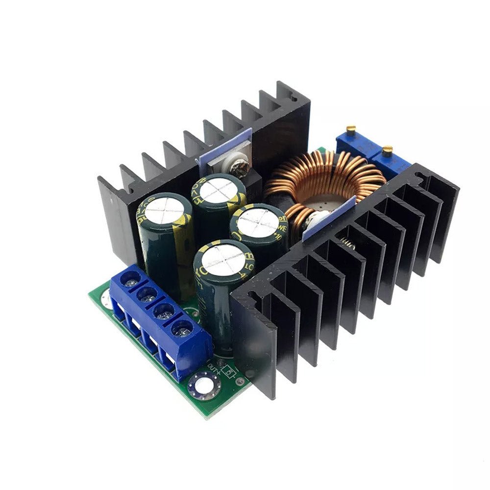
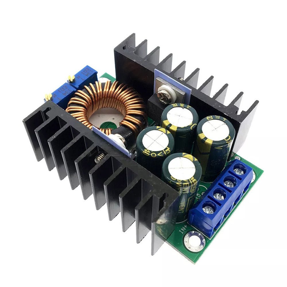
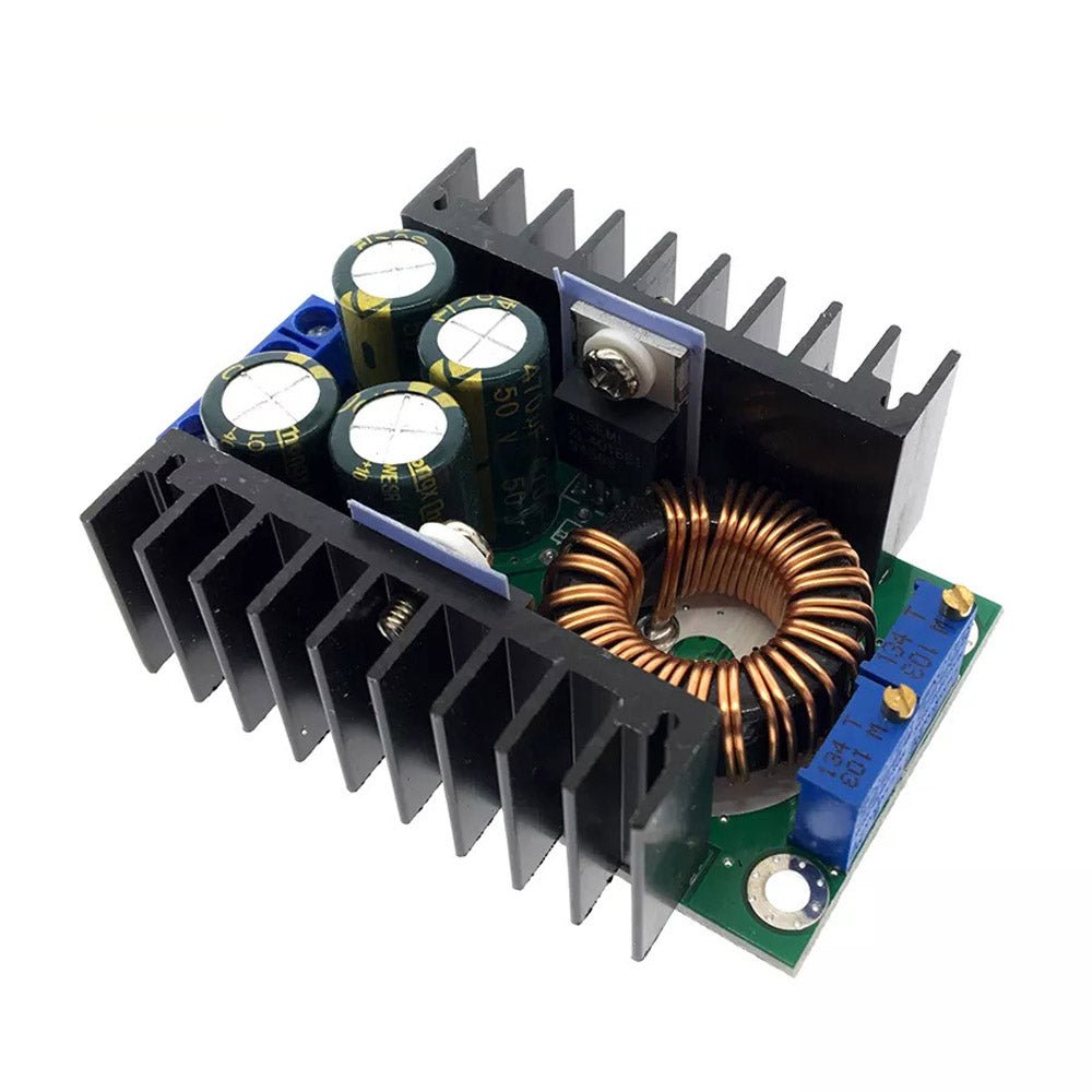
7-40V In 1.2-32V Out CC CV DC-DC Buck Step Down 8A 300W XL4016 Converter
7-40V In 1.2-32V Out CC CV DC-DC Buck Step Down 8A 300W XL4016 Converter
Couldn't load pickup availability
This 8A 300W DC-DC step-down (buck) converter provides a continuously variable output voltage of 1.2V to 32V DC at up to 8 Amps with an input voltage of 7V to 40V DC (input voltage must be at least ~1V greater than the output voltage).
This converter features Constant Voltage (CV) and Constant Current (CC) control. Featuring a high-precision current sensing resistor for stable constant current control with low-temperature drift and an advanced XL4016 PWM DC-DC converter, this module is perfect as an LED driver, battery charger, an automotive converter for converting 24V battery power to 6V, 12V, or 19V, or for other electronic applications requiring precision control of the output voltage and current. Its high operating frequency and output filter capacitors reduce output ripple, typically to 50mV at 12V, 5A output.
The bi-colored onboard LED provides quick visual confirmation of the module's status. Green indicates that power is on and the module is in open-circuit or constant voltage control mode. Red indicates the module is in constant current control.
Specifications:
- Type: Non-isolated step-down module, constant current and constant voltage module (CC CV) charging module
- Input Voltage: 7-40V DC
- Output voltage: 1.2-32V DC (continuously adjustable via onboard multi-turn potentiometer)
- Output Current: 8A Max (If the heatsink temperature exceeds 65C please add a cooling fan)
- Constant Current Range: 0.2-8A (continuously adjustable via the onboard potentiometer)
- Output Power: 300W maximum (If the heatsink temperature exceeds 65C please add a cooling fan)
- Conversion efficiency: Up to 95% (the higher output voltage, the higher the efficiency)
- Operating frequency: 180KHZ
- Output Ripple: Approximately 50mV at 24V Input, 12V Output at 5A
- Operating temperature: Industrial (-40C to +85C)
- No-load current: 20mA typical (24V Input, 12V Ouput)
- Load regulation: ± 1% ( constant voltage)
- Voltage regulation: ± 1%
- Constant current accuracy over temperature: Less than 5% variation from 25C to 60C (at a constant current value of 5A)
- Dynamic response speed: 5% 200uS
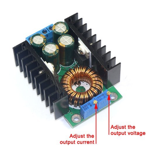
- Potentiometer adjustment: Clockwise (increase), counterclockwise (decrease). The potentiometer across from the input voltage connectors is for the voltage adjustment (CV), and the potentiometer across from the output voltage connectors is for current adjustment (CC)
- Indicator: Double-color LED. Green when the module is in constant voltage control or open-circuit (no load), red when in constant current control. For example, when charging a battery the indicator is RED, when fully charged it will switch to GREEN
- Output short circuit protection: Yes, through the constant current control (i.e. the constant current value you set limits the output current)
- Input Reverse Polarity Protection: None
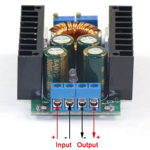
- Wiring: Terminal screws
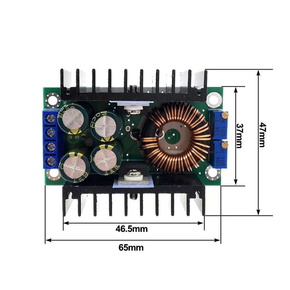
- Size: 2.6 x 1.8 x 0.9 inches (65 x 47 x 23.5 mm) LxWxH
Applications:
- High-power LED constant current driver
- Lithium, Nickel-Cadmium, Nickel-metal hydride or iron battery charger
- Solar panel and wind turbine output voltage/current control
- Automotive converter for converting 24V battery power to 6V, 12V, or 19V, or 12V battery power to 6V
- General-purpose power supply for electronic applications requiring constant voltage and/or constant current control
OPERATING INSTRUCTIONS:
Battery charger:
- Confirm the battery float voltage and charging current for your battery.
- With no load connected, set the output voltage to about 5V using the constant voltage potentiometer.
- Short the output connectors with a jumper and use a multimeter in 10A current scale to measure the output short-circuit current, and adjust the current potentiometer to set the short-circuit output current to the required charging current value.
- Remove the shorting jumper from the output and adjust the constant voltage potentiometer to set the output voltage to the battery's float voltage.
- Remove the input power from the converter, connect the output to the battery, and apply the input power. If the battery is charging the LED will be RED and will turn GREEN when charging is complete.
LED Constant Current Drive:
- Confirm the operating current and maximum operating voltage of the LED(s) you are driving.
- With no load connected, set the output voltage to about 5V using the constant voltage potentiometer.
- Short the output connectors with a jumper and use a multimeter in 10A current scale to measure the output short-circuit current, and adjust the current potentiometer to set the short-circuit output current to the required LED drive current.
- Remove the shorting jumper from the output and adjust the constant voltage potentiometer to set the output voltage to the LED's maximum operating voltage.
- Remove the input power from the converter, connect the output to the LED, and apply the input power to drive the LED(s).
- The module can drive multiple LEDs in series, parallel, or in series/parallel strings, as long as the maximum voltage and current of the string do not exceed the 32V maximum output voltage and 8A maximum output current of the driver module.
Solar panel, wind turbine, and other electronic applications:
Using the procedures outlined above, set the Constant Voltage (CV) and Constant Current (CC) levels required for your application. When powering microprocessors or other electronic devices, set the constant current (CC) to slightly above the devices' maximum current to protect the device from shorts, or over-power/over-dissipation conditions.
Operating Notes:
As with any DC-DC converter, the input DC power supply powering this converter must be capable of providing the maximum power drawn by your load. If the input supply is not capable of providing the power, the converter will fold back the output voltage as necessary. Example: If your load draws 3A at 5V (15W), and the input supply is only capable of providing 12V at 1A (12W), the maximum output voltage the converter will deliver is 4V (12W/3A).
Share
