3MM 4-Pin Common Anode Diffused RGB LED — Nipple Package | 5/10/25/100 Piece Pkgs
3MM 4-Pin Common Anode Diffused RGB LED — Nipple Package | 5/10/25/100 Piece Pkgs
Couldn't load pickup availability
📋 Overview
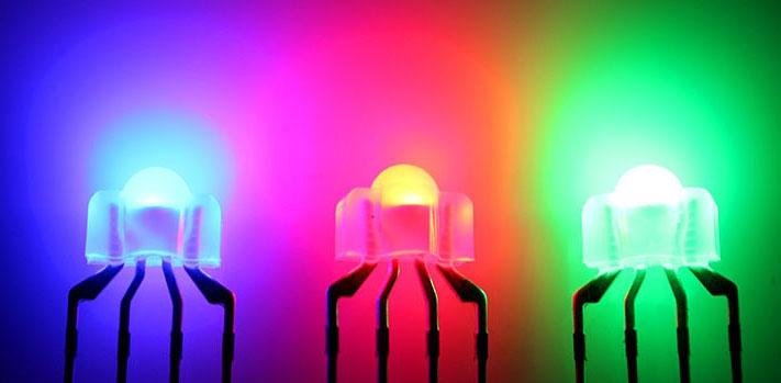
These 3mm nipple-package RGB LEDs pack three separate LEDs — red, green, and blue — into a single 4-pin component. By independently controlling the brightness of each channel with PWM (Pulse Width Modulation), you can mix virtually any color in the visible spectrum from a single LED. The diffused (frosted) lens scatters light from all three elements so they blend smoothly into a single uniform color rather than appearing as three distinct spots.
The common anode configuration means the shared positive lead (Lead 2, the longest pin) connects to your supply voltage, and each color is switched on by driving its cathode pin LOW. This is the standard configuration for per-key backlighting in mechanical keyboards, and these LEDs work equally well in breadboard prototypes, Arduino projects, panel indicators, and decorative lighting.
Available in 5, 10, 25, and 100-piece quantities to suit everything from a single prototype to a full keyboard build.
⭐ Key Features
- Three colors in one package — Red, green, and blue LEDs in a single 4-pin component
- Diffused (frosted) lens — Blends all three channels into smooth, uniform color output
- Common anode configuration — Longest lead is the shared positive; each color cathode switches independently
- Full-spectrum color mixing — Use PWM to set any brightness from 0–255 per channel and produce millions of color combinations
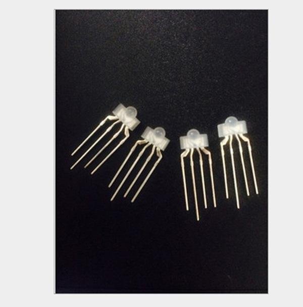
- 3mm nipple package — Standard size for per-key LED backlighting in mechanical keyboards
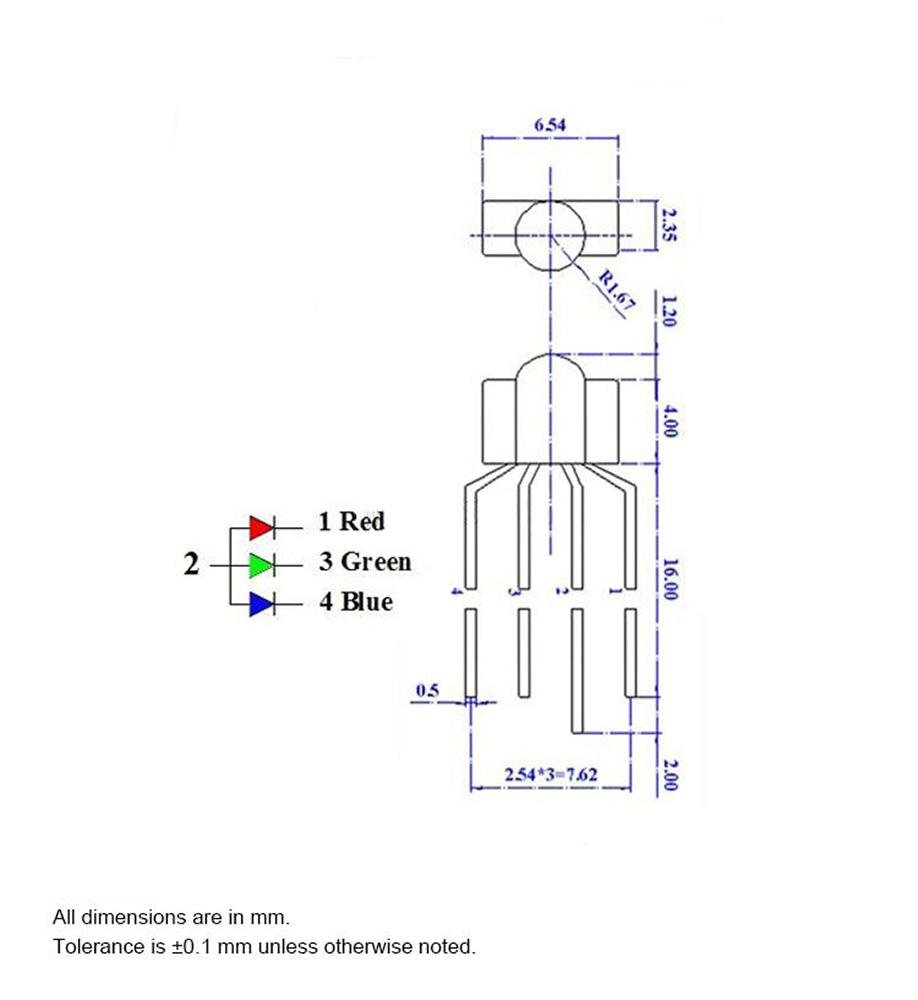
- RGB pin order — Lead 1 = Red, Lead 2 = Anode (+), Lead 3 = Green, Lead 4 = Blue
- Arduino and ESP32 compatible — Drive directly from PWM output pins with a series resistor per channel
- Low forward voltage — Red channel operates as low as 1.9V; green and blue at 3.0–3.3V
- RoHS compliant
- Quantity options — Available in 5, 10, 25, and 100-piece packs
📊 Specifications
| Parameter | Red | Green | Blue |
|---|---|---|---|
| Forward Voltage (Vf) at 20 mA | 1.9 – 2.1V (typ. 2.0V) | 3.1 – 3.3V (typ. 3.2V) | 3.0 – 3.2V (typ. 3.1V) |
| Dominant Wavelength | 620 – 625 nm | 520 – 525 nm | 460 – 470 nm |
| Luminous Intensity at 20 mA | 600 – 1000 mcd | 3000 – 4000 mcd | 600 – 800 mcd |
| Parameter | Value |
|---|---|
| Package Type | 3mm Nipple (Dome) |
| Lens Type | Diffused (frosted) |
| Configuration | Common Anode |
| Pin Count | 4 (Anode + R, G, B cathodes) |
| Maximum Working Current | 20 mA per color channel |
| Viewing Angle | 30° |
| Base Dimensions (excluding nipple) | Approx. 6.5 × 2.35 × 3.3 mm (0.26 × 0.09 × 0.13 inches) W × D × H |
| RoHS Compliant | Yes |
| Envistia Mall P/N | EM-LEDLI-0005-DI |
📦 What's in the Box
- 5-Pack: 5× 3MM 4-Pin Common Anode Diffused RGB LEDs
- 10-Pack: 10× 3MM 4-Pin Common Anode Diffused RGB LEDs
- 25-Pack: 25× 3MM 4-Pin Common Anode Diffused RGB LEDs
- 100-Pack: 100× 3MM 4-Pin Common Anode Diffused RGB LEDs
Note: Current-limiting resistors, Arduino, jumper wires, and breadboard are not included and must be purchased separately. See the Resistors section below for recommended values.
📌 Pinout
Hold the LED with the flat side of the base facing you and the leads pointing down. Leads are numbered left to right, 1 through 4. Lead 2 is the longest — this is the common anode (+).
| Lead # | Function | Notes |
|---|---|---|
| Lead 1 | Red cathode (−) | Connect through a resistor to GND (or a PWM output pin for variable brightness). |
| Lead 2 | Common anode (+) — longest lead | Connect to your positive supply voltage (5V recommended). |
| Lead 3 | Green cathode (−) | Connect through a resistor to GND (or a PWM output pin). |
| Lead 4 | Blue cathode (−) | Connect through a resistor to GND (or a PWM output pin). |
Common Anode PWM Note: Because the anode is shared and tied to +V, the control logic is inverted.
analogWrite(pin, 0)= full brightness;analogWrite(pin, 255)= off. See the User Guide for sample Arduino code that handles this automatically.
🔋 Current-Limiting Resistors
Each color channel requires its own current-limiting resistor in series between the cathode lead and GND (or the PWM output pin). Never connect an LED without a resistor — unprotected LEDs draw excessive current instantly and will burn out.
Resistor value formula: R = (Vs − Vf) / If
The table below gives recommended values for the most common supply voltages. Running at 10 mA is recommended for general use — it extends LED life and stays safely within Arduino output pin current limits.
| Supply Voltage | Target Current | Red (Lead 1) | Green (Lead 3) | Blue (Lead 4) |
|---|---|---|---|---|
| 5V | 20 mA (maximum rated) | 150Ω | 100Ω | 100Ω |
| 5V | 10 mA (recommended) | 300Ω | 180Ω | 180Ω |
| 3.3V | 10 mA | 130Ω | 33Ω ⚠️ | 33Ω ⚠️ |
⚠️ 3.3V Warning: The forward voltage of green (3.1–3.3V) and blue (3.0–3.2V) is very close to 3.3V, leaving very little headroom for current limiting. At 3.3V, use at least 33Ω on green and blue and expect noticeably reduced brightness on those channels. A 5V supply is strongly recommended for full brightness on all three channels.
🔌 Wiring to Arduino
Connect Lead 2 (anode, longest) to the Arduino's 5V pin. Connect each color cathode through its resistor to a PWM-capable pin. On Arduino Uno and Nano, PWM pins are marked with a tilde (~): pins 3, 5, 6, 9, 10, and 11.
| LED Lead | Arduino Connection |
|---|---|
| Lead 2 (Anode, longest) | 5V |
| Lead 1 (Red cathode) | 150Ω resistor → PWM Pin 9 |
| Lead 3 (Green cathode) | 100Ω resistor → PWM Pin 10 |
| Lead 4 (Blue cathode) | 100Ω resistor → PWM Pin 11 |
🎨 Color Mixing Quick Reference
Use these PWM values (0 = off, 255 = full brightness) with the setColor(red, green, blue) helper function in our User Guide's sample code. The function handles the common-anode inversion automatically.
Green brightness tip: Green is 3–6× brighter than red or blue at the same current. For a balanced white, try reducing green to around 120 while keeping red and blue at 255, then adjust to taste.
| Color | Red | Green | Blue |
|---|---|---|---|
| Red | 255 | 0 | 0 |
| Green | 0 | 255 | 0 |
| Blue | 0 | 0 | 255 |
| Yellow | 255 | 255 | 0 |
| Cyan | 0 | 255 | 255 |
| Magenta | 255 | 0 | 255 |
| White (nominal) | 255 | 255 | 255 |
| White (green-adjusted) | 255 | 120 | 255 |
| Orange | 255 | 165 | 0 |
| Purple | 128 | 0 | 128 |
⌨️ Keyboard Builders — RGB vs. RBG Pin Order
This LED follows the RGB pin order: Lead 1 = Red, Lead 2 = Anode (+), Lead 3 = Green, Lead 4 = Blue. Some keyboard PCBs are designed for RBG LEDs, where green and blue are swapped (Lead 3 = Blue, Lead 4 = Green).
Using an RGB LED in an RBG-wired PCB will not damage anything, but colors will be incorrect — green and blue will be reversed in all color outputs. Red always displays correctly regardless of type. Always verify your keyboard PCB's required LED type before ordering.
How to check: Consult your keyboard PCB documentation, check the silkscreen markings near the LED footprint, or search your keyboard model in enthusiast forums like r/MechanicalKeyboards. See the User Guide for a full RGB vs. RBG comparison and compatibility notes.
🎯 Applications
- Mechanical keyboard per-key backlighting — Standard 3mm nipple form factor fits most keyboard switch openings
- Arduino and microcontroller color projects — Color mixing, PWM control, and learning electronics fundamentals
- Status and indicator lights — Color-coded alerts, system state indicators, and multi-state signals
- Panel mount indicators — DIY enclosures and custom control panels
- Decorative and ambient lighting — Low-power color accent and mood lighting
- Educational kits — Teaching RGB color theory, PWM, and LED circuits
- Prototyping and maker projects — Available in multi-packs for builds requiring multiple LEDs
⚠️ Important Notes
- Always use a current-limiting resistor on every color cathode. Connecting without a resistor will immediately burn out the LED.
- Do not exceed 20 mA per color channel. Running at 10 mA is recommended for longer LED life.
- Each channel requires its own separate resistor — do not share one resistor across multiple color leads.
- Each color has a different forward voltage — calculate resistor values individually for red, green, and blue.
- Green is significantly brighter than red and blue at equal currents. Reduce the green PWM value when aiming for balanced white or neutral colors.
- At 3.3V, green and blue channels have very little voltage headroom. A 5V supply is preferred for full brightness on all channels.
- Verify your keyboard PCB's required LED type (RGB vs. RBG) before installing — using the wrong type produces reversed green and blue colors.
📄 Documentation & Resources
- User Guide — Pinout, Resistor Calculations, Arduino Code, Color Mixing & Keyboard Compatibility
- All Laser & LED Guides
Sold and supported by Envistia Mall. Ships from the USA. For pinout diagrams, resistor calculations, sample code, and troubleshooting, see the User Guide link on this product page. The manufacturer and Envistia LLC (dba Envistia Mall) are not responsible for any damages or losses resulting from the use of this product. Always follow proper electrical safety practices when working with electronic components. Specifications are based on manufacturer data and are subject to change without notice.
Share