


A4988 Stepper Motor Driver with Expansion Board — Solderless JST Motor Connection, DIP Switch Microstepping, Arduino Compatible
A4988 Stepper Motor Driver with Expansion Board — Solderless JST Motor Connection, DIP Switch Microstepping, Arduino Compatible
Couldn't load pickup availability
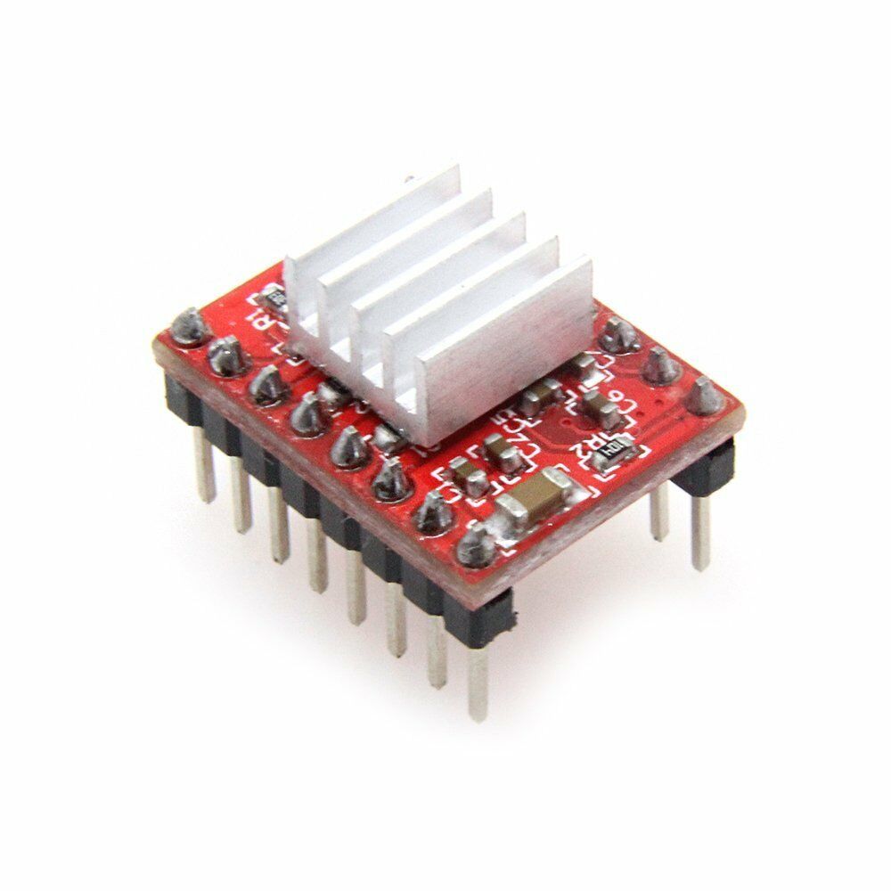
Stop wrestling with loose jumper wires and breadboard connections. This A4988 Stepper Motor Driver with Expansion Board combines Allegro's proven A4988 microstepping driver with a purpose-built breakout board that gives you clean, solderless connections for your motor, power supply, and control signals — all through dedicated connectors and onboard DIP switches. The A4988 driver plugs into the expansion board via header sockets, so you can easily swap or replace drivers without soldering.
⚡ Why Choose the Expansion Board Kit vs. the Standalone A4988 Module?
- JST motor connector — Plug your stepper motor directly into the onboard JST XHP-4 socket. No soldering, no loose wires, no missed connections. Solder pads are also provided if you prefer a permanent connection.
- DIP switch microstepping — Set your microstepping resolution (full, 1/2, 1/4, 1/8, 1/16) with three onboard DIP switches instead of fiddling with jumper wires on tiny MS1/MS2/MS3 pins.
- Organized pin headers — Separate headers for power (5V logic + 8–35V motor supply) and control signals (Enable, Step, Dir, GND) keep your wiring clean and your project professional.
- Swappable driver — The A4988 module plugs into header sockets on the expansion board. If a driver fails, swap it in seconds — no desoldering required.
- Heatsink included — Achieve up to 2A per phase with the included heatsink; 1A continuous without additional cooling.
🔧 How It Works
- Plug in the A4988 driver module — Insert the included A4988 module into the expansion board's header sockets (align the potentiometer toward the motor connector end).
- Attach the heatsink — Peel and stick the included adhesive heatsink onto the A4988 driver IC.
- Connect power — Wire your 8V–35V motor power supply and 5V logic supply to the power header (Jv).
- Connect your motor — Plug your bipolar stepper motor's JST XHP-4 connector into the motor socket (Jm), or solder motor wires to the provided pads. Pins map to: 1B, 1A, 2A, 2B.
- Set microstepping — Use the three onboard DIP switches to select your desired resolution (see table below).
- Set current limit — Adjust the A4988's onboard potentiometer. Measure VREF with a multimeter: Current Limit = VREF × 2.5.
- Wire to your controller — Connect Enable, Step, Dir, and GND from the control header (Jc) to your Arduino or microcontroller. Only Step and Dir are required for basic operation.
Microstepping Resolution — DIP Switch Settings
| SW1 (MS1) | SW2 (MS2) | SW3 (MS3) | Resolution |
|---|---|---|---|
| OFF | OFF | OFF | Full Step |
| ON | OFF | OFF | 1/2 Step |
| OFF | ON | OFF | 1/4 Step |
| ON | ON | OFF | 1/8 Step |
| ON | ON | ON | 1/16 Step |
🎯 Perfect For
- Arduino stepper motor projects — Clean wiring with dedicated connectors eliminates breadboard spaghetti.
- 3D printer builds & upgrades — Reliable motor connections for custom or DIY printer electronics.
- CNC machines — Drive NEMA 17 and smaller NEMA 23 motors for routers, laser cutters, and engravers.
- Robotics & automation — Precise positioning for robotic arms, turntables, and linear actuators.
- STEM education — DIP switches and labeled connectors make it easier for students to understand stepper motor control.
- Prototyping & testing — Swappable driver and solderless connections speed up development cycles.
📐 Specifications
Expansion Board
- Motor connector: JST XHP-4 socket (solderless) + solder pads
- Power header (Jv): 5V logic + 8–35V motor supply
- Control header (Jc): Enable, Step, Dir, GND
- Microstepping selection: 3-position DIP switch (MS1, MS2, MS3)
- Driver interface: Header sockets (plug-in, no soldering)
- Board dimensions: 43mm × 35mm × 10mm (excluding A4988 module)
A4988 Driver Module
- Driver IC: Allegro A4988 DMOS Microstepping Driver
- Motor supply voltage: 8V – 35V
- Logic voltage: 3V – 5.5V
- Continuous current per phase: 1A (no heatsink)
- Maximum current per phase: 2A (with heatsink / active cooling)
- Microstep resolutions: Full, 1/2, 1/4, 1/8, 1/16
- Current adjustment: Onboard potentiometer (VREF)
- Protection: Thermal shutdown, overcurrent, ground fault, load short-circuit
📦 Package Contents
- 1 × A4988 Expansion / Breakout Board
- 1 × A4988 Stepper Motor Driver Module
- 1 × Adhesive Heatsink
Stepper motor, power supply, microcontroller, and JST motor cable are not included.
📄 Documentation & Resources
Share


Works and got me through my senior design project
If you are needing to drive a NEMA 17 motor up to 1 or maybe 2 Amps this driver module may be just what you need. I have seen a lot of reviews that mention module overheating and motors that just vibrate or run erratically when connected to the module and I have to say the same thing happened to me. It wasn’t the driver module’s fault though. I found that if you crank the reference voltage potentiometer fully counterclockwise before ever connecting power and then easing it up clockwise incrementally once power is applied and monitoring the stepper motor coil amperage you will avoid the overheating issue. The buzzing motor, or erratic operation issue occurs if you don’t connect the motor windings up to the driver outputs 1A, 1B, 2A, and 2B correctly. StepperOnline labels the windings as A+, A-, B+, and B-. If you connect A+ to 1A, A- to 1B, B+ to 2A, and B- to 2B things work as you would expect. Once I figured this out I was able to drive the motor to 0.6A under full load (stalled motor armature) for several minutes with no signs of overheating in the driver module or the stepper motor. My power supply could only drive 12 volts at 0.6A so I couldn’t push things any higher but since things stayed cool and stable at those levels (except for my power supply!) I am pretty confident that when my new power supply comes in I will still be OK at 1.5 to 2 amps. Will come back and edit this review if I find out otherwise. At this point though, I am very satisfied with the A4988 stepper motor driver! One other note - one of the two tantalum capacitors I had in parallel across the motor supply power connectors in the photo exploded like a firecracker during this testing. And, no, I didn’t have the polarity wrong on the one that exploded. They were both rated at 33uF and 35 volts. Switched to a 2200uF 50v electrolytic and it help up just fine. Guessing that transients generated by the motor windings exceeded the voltage rating and caused the poor little bugger to short out and over heat.
I was given a 3D printer that did not work correctly. The filament was not advancing. I replaced the stepper driver with this one, and it started working.
Exactly what I needed! Worked perfectly. Love that it’s a 2 pack so I have a backup on hand in case any other issues arise unexpectedly.