
Digispark ATtiny85 USB-C Development Board — Arduino Compatible Microcontroller
Digispark ATtiny85 USB-C Development Board — Arduino Compatible Microcontroller
Couldn't load pickup availability
💡 Overview
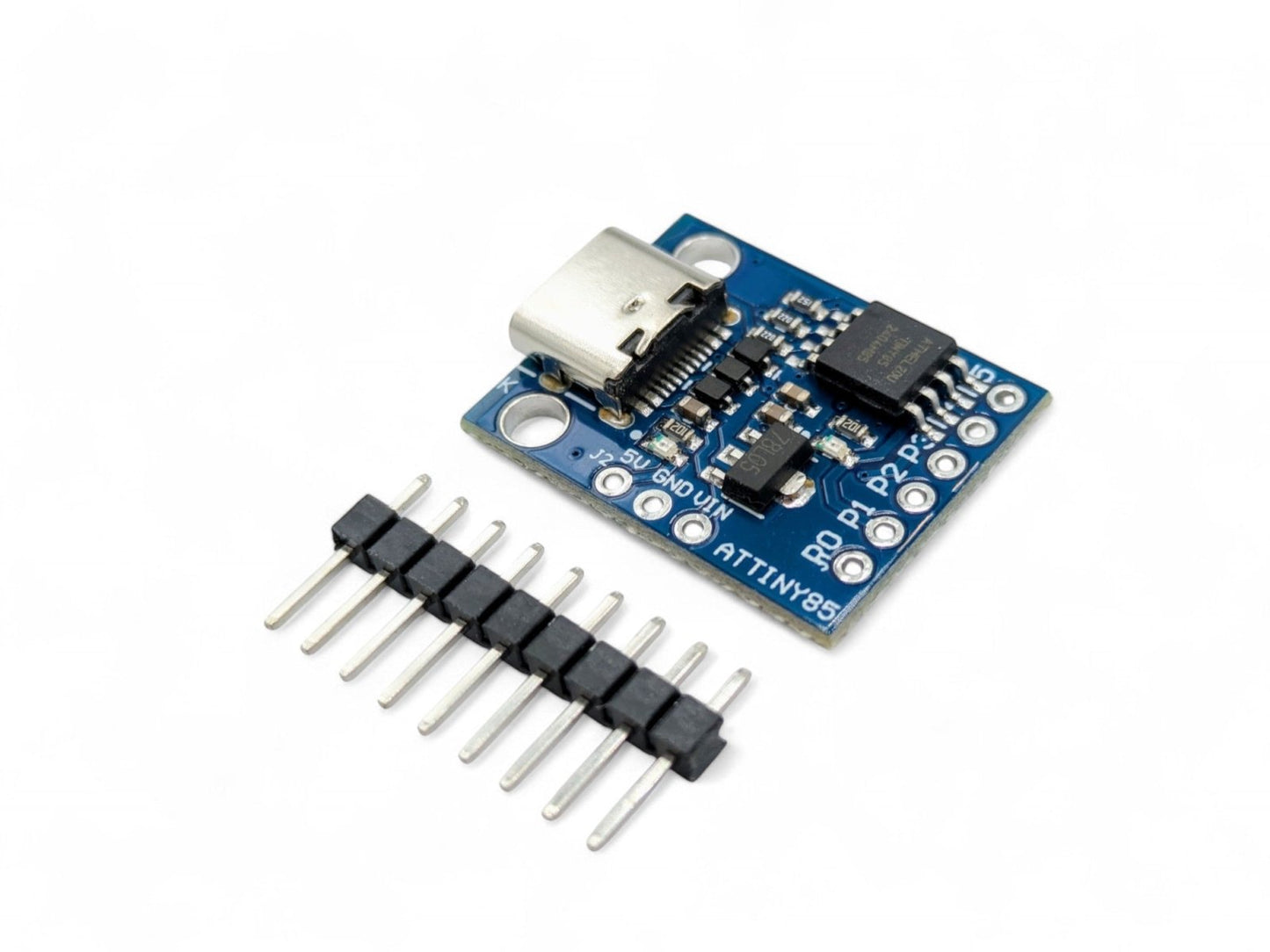
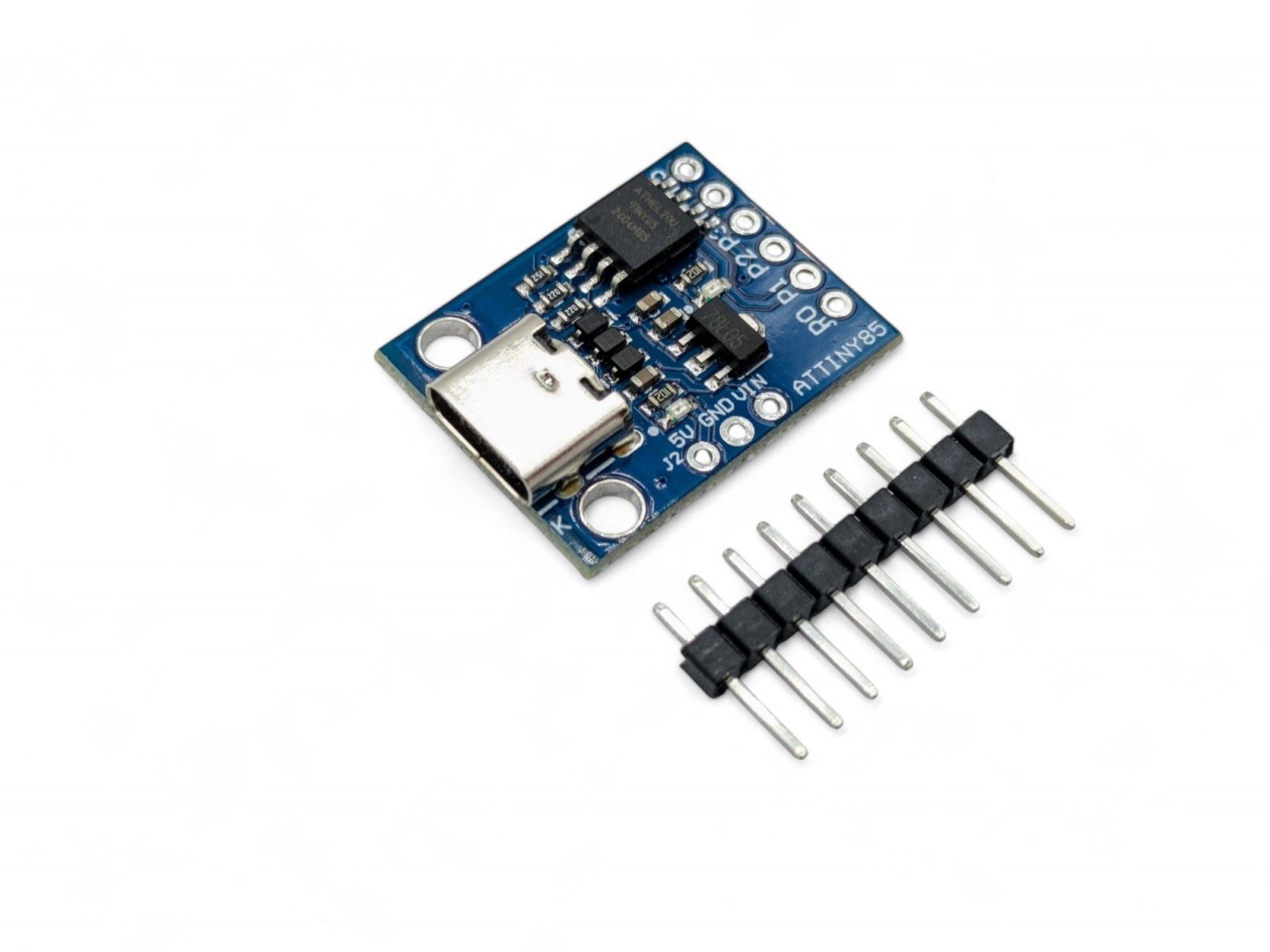
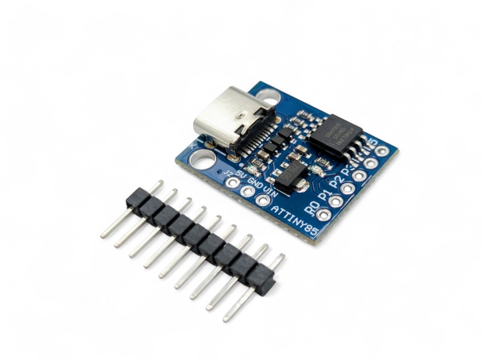
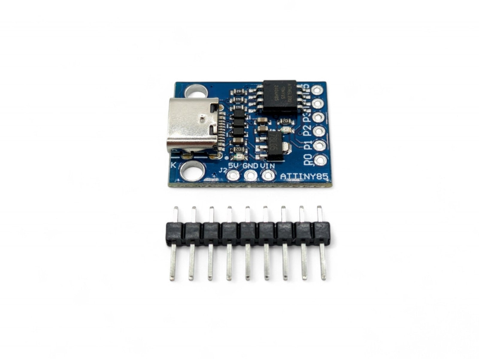
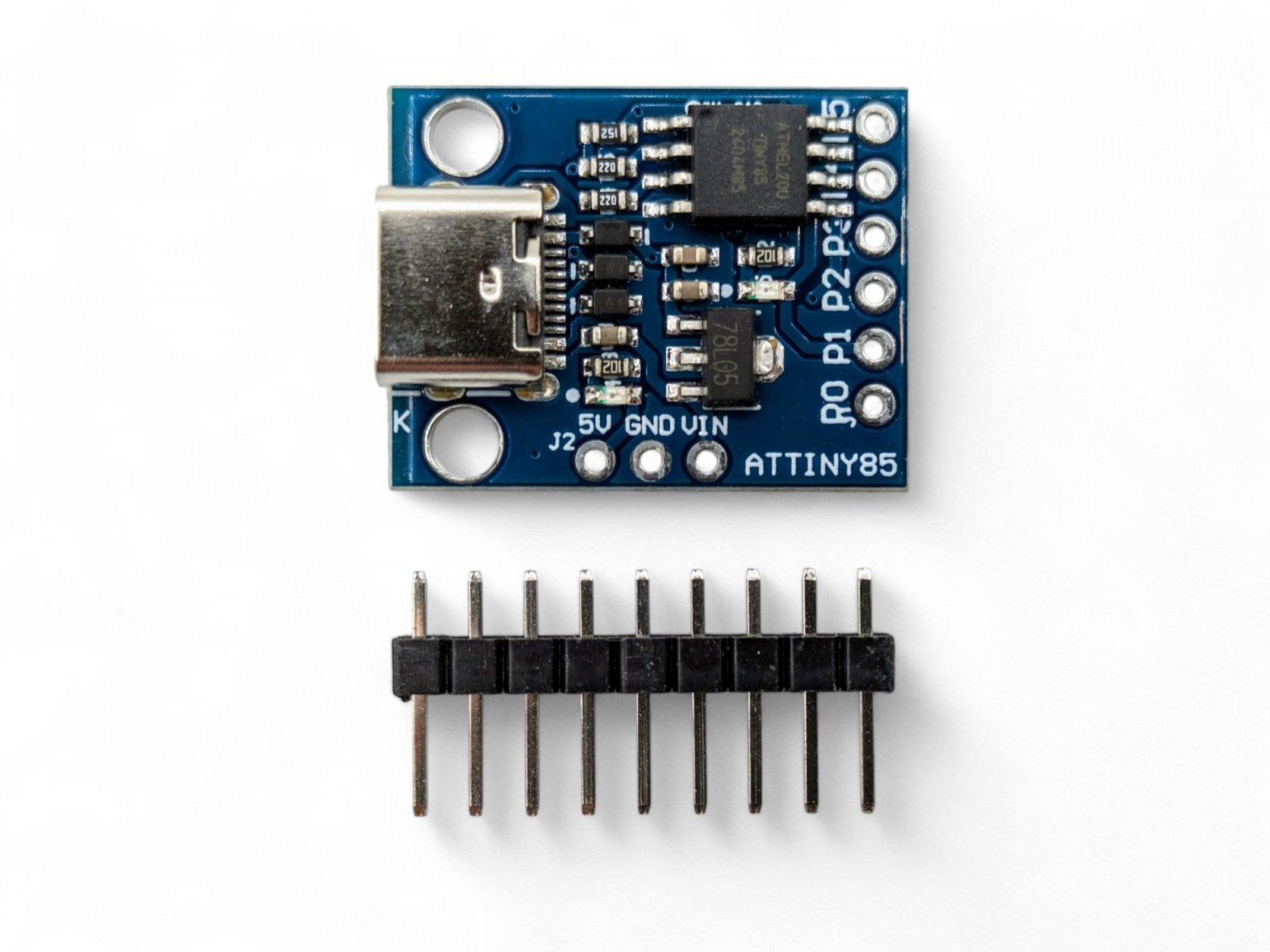
The Digispark ATtiny85 USB-C is a modern take on the popular Digispark development board, replacing the traditional USB-A plug with a standard USB-C connector. This means you can connect it to your computer using any USB-C cable — no adapters needed for modern laptops and desktops. It uses the same Microchip ATtiny85 microcontroller, the same Micronucleus USB bootloader, and is programmed the same way through the Arduino IDE.
The USB-C connector also makes the board more practical for deployed projects, since you can easily disconnect and reconnect using a standard cable rather than unplugging the entire board from a USB port.
⭐ Key Features
- Modern USB-C Connector — Connect with any standard USB-C cable; no adapters needed for modern computers
- Ultra-Compact Design — Tiny form factor perfect for embedding into small enclosures and portable projects
- Arduino IDE Compatible — Program using the familiar Arduino IDE with Digistump board support
- Micronucleus USB Bootloader — No external programmer required; upload sketches directly over USB
- 6 I/O Pins — Supports digital I/O, PWM (3 pins), and analog input (4 channels)
- On-Board LED — Built-in LED on pin P1 for easy testing and debugging
- On-Board 5V Regulator — Can also be powered via VIN pin (7–12V) for standalone projects
- USB HID Capable — Can emulate USB keyboards, mice, and other HID devices
- Easy Cable Connection — More convenient than the USB-A version for repeated connect/disconnect cycles
📋 Specifications
| Parameter | Value |
|---|---|
| Microcontroller | Microchip ATtiny85 |
| Architecture | 8-bit AVR |
| Clock Speed | 16.5 MHz (internal PLL) |
| Flash Memory | 8 KB (~6 KB available after bootloader) |
| SRAM | 512 bytes |
| EEPROM | 512 bytes |
| Digital I/O Pins | 6 (P0–P5) |
| PWM Outputs | 3 (P0, P1, P4) |
| Analog Input Channels | 4 (P2, P3, P4, P5) |
| Operating Voltage | 5V |
| Input Voltage (VIN) | 7–12V |
| USB Interface | USB-C connector (USB 1.1 Low Speed) |
| Bootloader | Micronucleus (V-USB based) |
| On-Board LED | Yes — connected to P1 |
| Board Dimensions | Approx. 24 × 18 mm (0.95 × 0.71 inches) L × W |
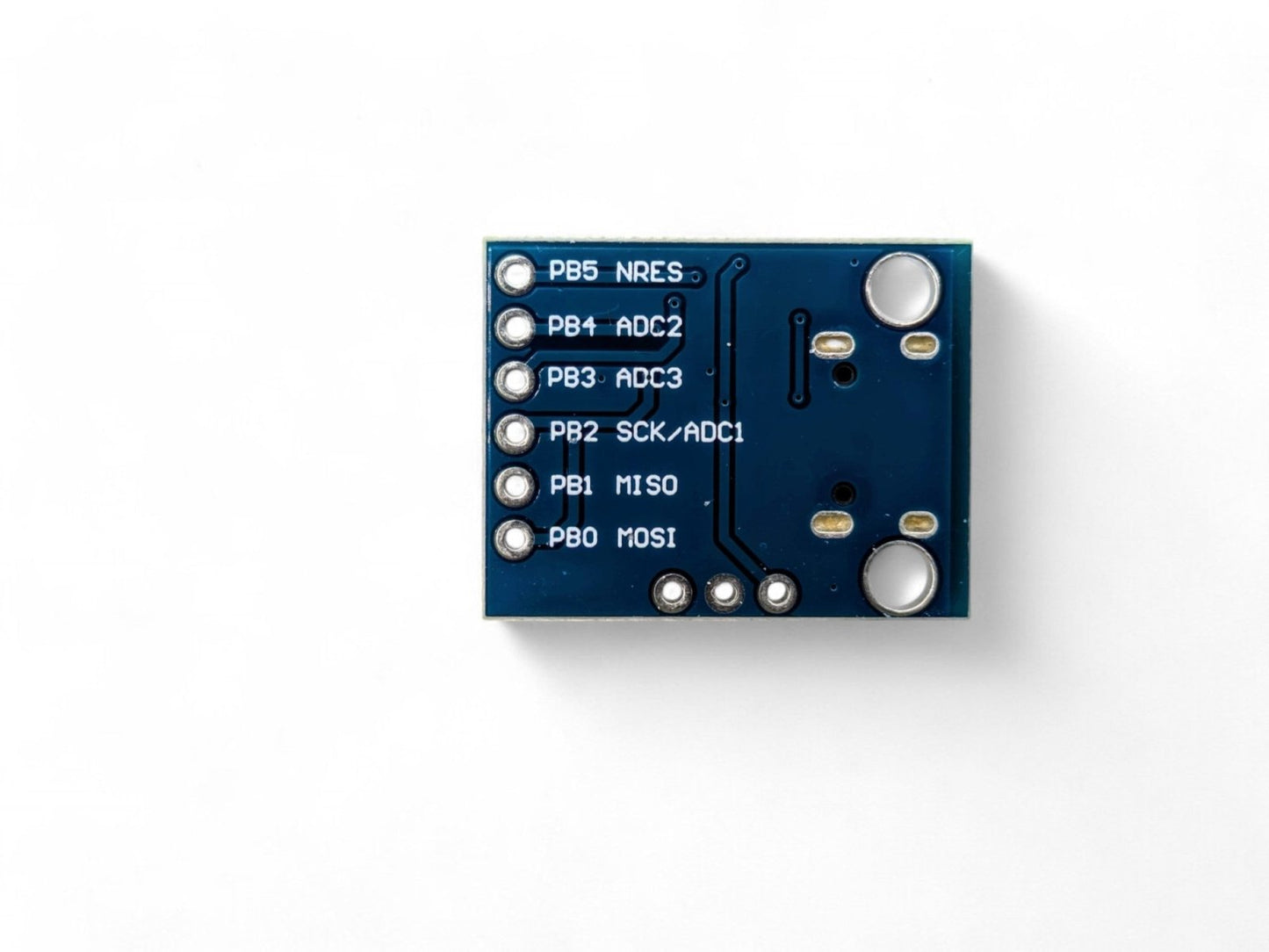
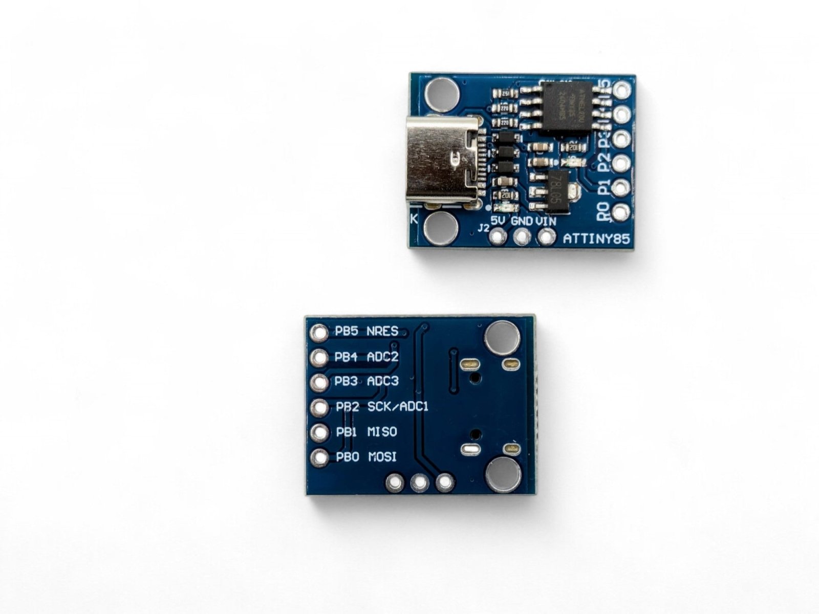
📌 Pin Configuration
| Pin | Digital I/O | PWM | Analog In | Special Function |
|---|---|---|---|---|
| P0 | Yes | Yes | — | SDA (I2C), MOSI (SPI) |
| P1 | Yes | Yes | — | MISO (SPI), On-Board LED |
| P2 | Yes | — | A1 | SCL (I2C), SCK (SPI) |
| P3 | Yes | — | A3 | USB D+ |
| P4 | Yes | Yes | A2 | General Purpose (safest pin) |
| P5 | Yes | — | A0 | RESET (do not reconfigure) |
🎯 Typical Applications
- USB HID devices — custom keyboards, macros, shortcuts, and mouse emulators
- LED controllers and RGB lighting effects
- Sensor data logging (temperature, light, humidity)
- Wearable electronics and compact embedded projects
- Home automation triggers and IoT sensor nodes
- Educational projects and learning Arduino programming
- Rapid prototyping of simple control circuits
📦 What's in the Box
- 1 × Digispark ATtiny85 Development Board (USB-C)
- Header pins (require soldering)
Note: USB-C cable not included. Use any standard USB-C data cable.
⚠️ Important Notes
- The Digispark uses a unique upload process: click Upload in the Arduino IDE first, then plug in the board when prompted. The bootloader only listens for new code for ~5 seconds after power-on. See the User Guide for more details and extensive programming instructions.
- Use a data-capable USB-C cable, not a charge-only cable. Charge-only cables will not work for programming.
- Windows users must install Digistump USB drivers before first use. See the User Guide for instructions.
- The ATtiny85 does not have a hardware UART — the standard Arduino Serial Monitor is not available.
- With ~6 KB of usable flash memory, keep sketches small and avoid large libraries.
- Pin P5 is the RESET pin. Reconfiguring it as I/O will permanently disable USB programming.
- For best results, use a USB 2.0 port or hub. Some USB 3.0 controllers may have compatibility issues with low-speed USB devices.
📄 Documentation & Resources
For detailed setup instructions, Arduino IDE configuration, driver installation, wiring diagrams, and example projects, see our comprehensive User Guide:
Sold and supported by Envistia Mall. Ships from the USA. For wiring diagrams and troubleshooting, see the User Guide. The manufacturer and Envistia LLC (dba Envistia Mall) are not responsible for any damages or losses resulting from the use of this product. Always follow proper electrical safety practices when working with electronic components. Specifications are based on manufacturer data and are subject to change without notice.
Share