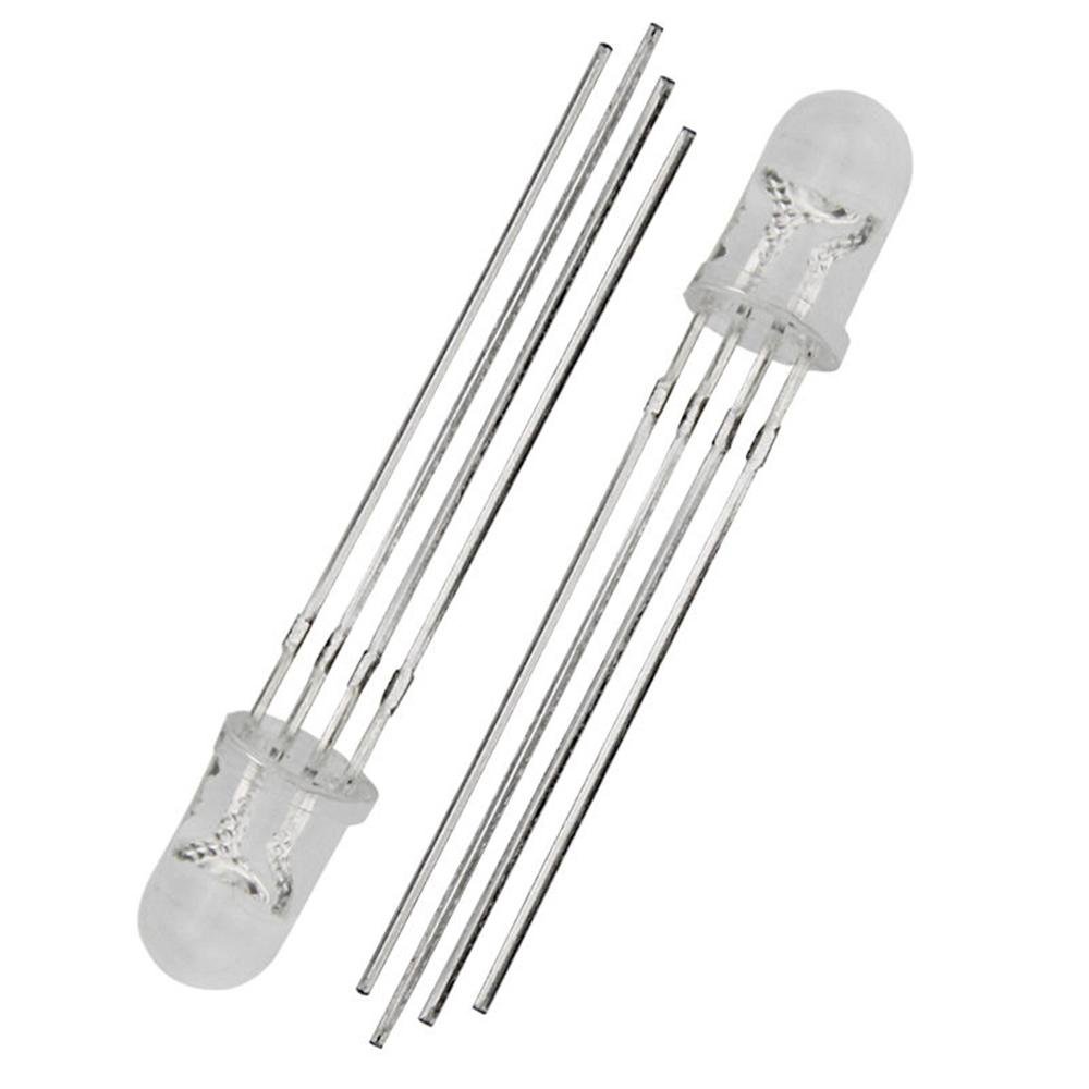
5mm Common Anode Clear RGB LED - 4-Pin Tri-Color Red Green Blue LED Diodes (5/10/25 Pieces)
5mm Common Anode Clear RGB LED - 4-Pin Tri-Color Red Green Blue LED Diodes (5/10/25 Pieces)
Couldn't load pickup availability
📋 Overview
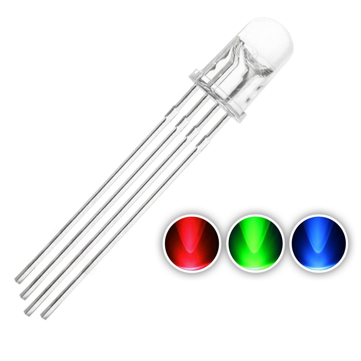
These 5mm clear-lens RGB LEDs pack three colors — red, green, and blue — into a single 4-pin package. By controlling each color independently with PWM, you can produce virtually any color in the visible spectrum. The clear lens delivers a focused, directional beam with a 60° viewing angle, making these LEDs ideal for indicator lights, directional signals, and projects where a bright, concentrated point of light is needed.
These are common anode LEDs — the longest pin is the shared positive (+) connection, and each color is activated by pulling its cathode pin LOW through a current-limiting resistor. Sold in convenient 5-, 10-, & 25-piece packs.
⭐ Key Features
- Three Colors in One — Red, green, and blue LEDs in a single 5mm package
- Common Anode Configuration — Shared positive pin for simplified wiring
- Clear Lens — Focused, directional beam with 60° viewing angle
- Full Color Mixing — Combine RGB values via PWM to create any color
- High Brightness — Up to 5000 mcd (green channel)
- Standard 5mm (T1-3/4) Package — Fits standard LED holders and breadboards
- Low Power — 20mA per color channel
- Arduino & Microcontroller Compatible — Works with any platform that supports PWM output
📊 Specifications
| Parameter | Value |
|---|---|
| Package Size | 5mm (T1-3/4) |
| Lens Type | Clear (water clear) |
| Configuration | Common Anode |
| Number of Pins | 4 |
| Forward Voltage — Red | 2.25V |
| Forward Voltage — Green | 3.5V |
| Forward Voltage — Blue | 3.5V |
| Wavelength — Red | 630–640 nm |
| Wavelength — Green | 515–525 nm |
| Wavelength — Blue | 465–475 nm |
| Luminous Intensity — Red | 1000–1200 mcd |
| Luminous Intensity — Green | 3000–5000 mcd |
| Luminous Intensity — Blue | 2000–3000 mcd |
| Viewing Angle | 60° |
| Forward Current (per channel) | 20mA |
| Reverse Current | 100µA max |
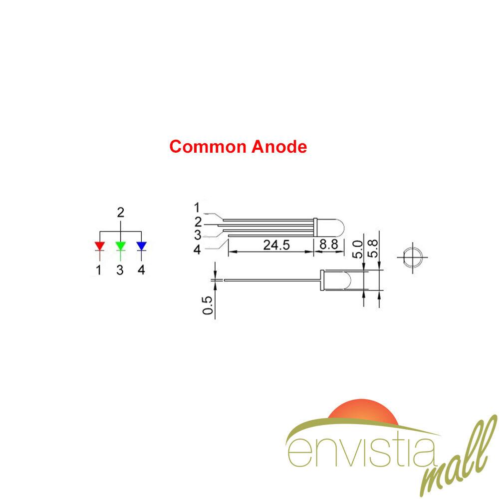
📌 Pinout
The LED has 4 pins. The longest pin is the common anode (+V). With the LED facing you (lens on top) and the flat side of the lens to the right:
| Pin | Position | Function |
|---|---|---|
| 1 | Far left | Red cathode (−) |
| 2 | Center-left (longest) | Common Anode (+V) |
| 3 | Center-right | Green cathode (−) |
| 4 | Far right | Blue cathode (−) |
🔌 Wiring
Connect the common anode (longest pin) to your +5V supply. Each color cathode connects to a PWM-capable GPIO pin on your microcontroller through a current-limiting resistor. The LED turns on when the cathode pin is pulled LOW.
Recommended Resistor Values (5V Supply, 20mA)
| Color | Minimum Resistor | Recommended |
|---|---|---|
| Red | 137.5Ω | 150Ω |
| Green | 75Ω | 100Ω |
| Blue | 75Ω | 100Ω |
💡 Tip: A 220Ω resistor on all three channels is a safe, universal choice if you don't need maximum brightness.
🚀 Getting Started
Connect the LED to an Arduino using PWM pins (e.g., D9, D10, D11). Since this is a common anode LED, the PWM logic is inverted — a value of 0 = full brightness and 255 = off.
// Common Anode RGB LED — Quick Test
const int redPin = 9, greenPin = 10, bluePin = 11;

void setup() {
  pinMode(redPin, OUTPUT);
  pinMode(greenPin, OUTPUT);
  pinMode(bluePin, OUTPUT);
}

void loop() {
  analogWrite(redPin, 0); analogWrite(greenPin, 255); analogWrite(bluePin, 255); // Red
  delay(1000);
  analogWrite(redPin, 255); analogWrite(greenPin, 0); analogWrite(bluePin, 255); // Green
  delay(1000);
  analogWrite(redPin, 255); analogWrite(greenPin, 255); analogWrite(bluePin, 0); // Blue
  delay(1000);
  analogWrite(redPin, 0); analogWrite(greenPin, 0); analogWrite(bluePin, 0);     // White
  delay(1000);
}
🔌 Compatible With
- Arduino (Uno, Mega, Nano, etc.)
- ESP32 / ESP8266
- Raspberry Pi Pico
- STM32 and other microcontrollers with PWM output
- Any 3.3V–5V digital logic system (5V recommended for full brightness)
🎯 Typical Applications
- Status indicators with color-coded feedback
- Mood and ambient lighting projects
- LED art installations and displays
- Robotics visual feedback
- Wearable electronics
- Educational projects for learning PWM and color theory
- Prototyping color feedback systems
📦 What's in the Box
- 5/10/25x 5mm Common Anode Clear RGB LED Diodes - quantity selected above
Current-limiting resistors are not included. See the Wiring section above and the User Guide linked below for recommended values.
💡 Tips
- The green channel is significantly brighter than red — reduce green/blue PWM values when mixing to achieve balanced white or pastel colors.
- Clear-lens LEDs produce a focused beam — ideal for indicator lights but can be intense to look at directly. Consider diffused LEDs for softer, more evenly distributed light.
- On 3.3V systems, the green and blue channels (Vf = 3.5V) may not light reliably. Use a 5V supply for full-color operation.
- Use a helper function to invert PWM values so you can write standard 0–255 logic:
analogWrite(pin, 255 - value);
⚠️ Important Notes
- Always use current-limiting resistors — driving an LED without one will destroy it.
- Do not exceed 20mA forward current per color channel.
- Observe correct polarity — the common anode pin connects to positive voltage, not ground.
- These LEDs are not waterproof.
📄 Documentation & Resources
For detailed wiring diagrams, resistor calculations, Arduino code examples, and color mixing tutorials, see our full User Guide:
Sold and supported by Envistia Mall. Ships from the USA. For wiring diagrams and troubleshooting, see the User Guide. The manufacturer and Envistia LLC (dba Envistia Mall) are not responsible for any damages or losses resulting from the use of this product. Always follow proper electrical safety practices when working with electronic components. Specifications are based on manufacturer data and are subject to change without notice.
Share