


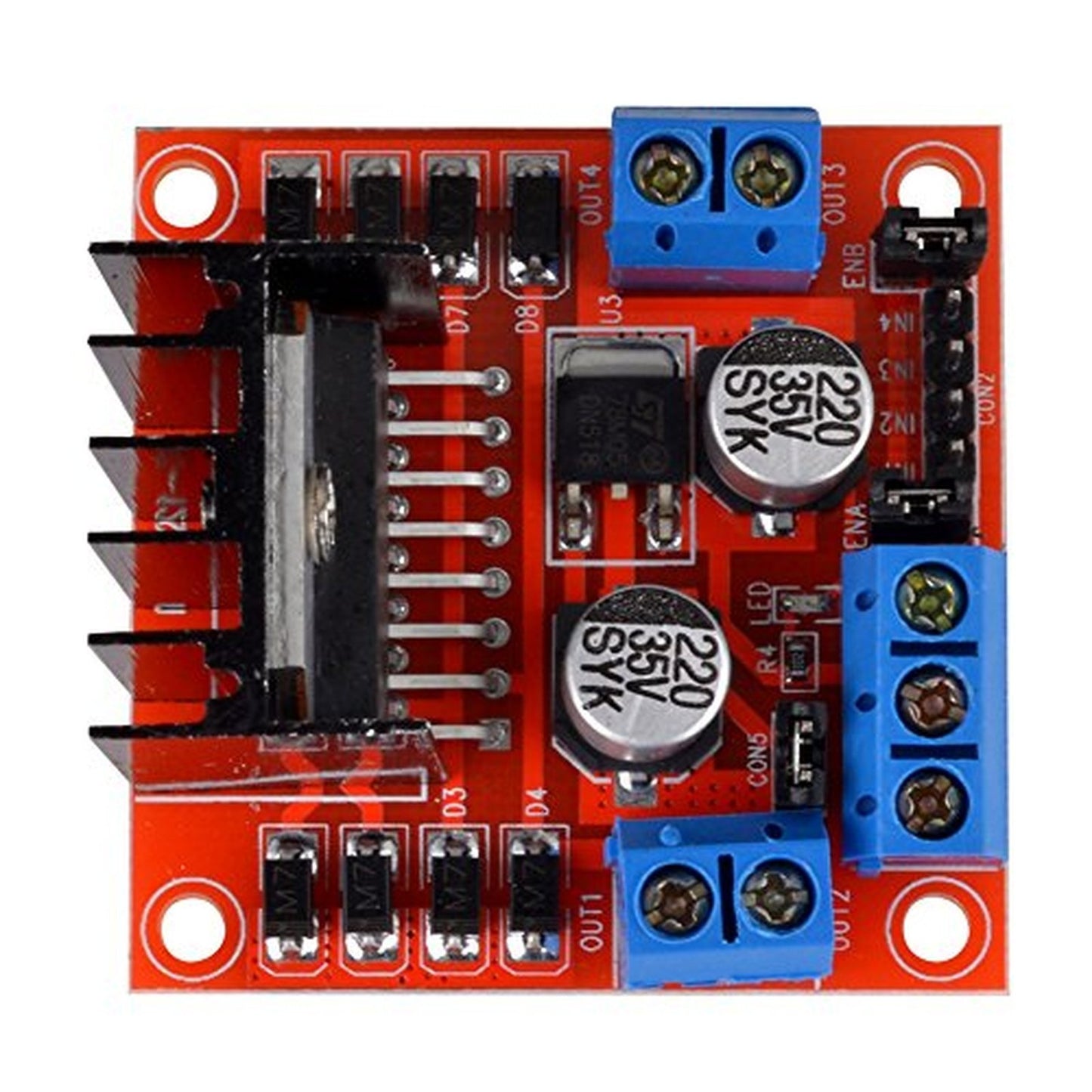
L298N Dual H-Bridge PWM DC & Stepper Motor Driver Controller Module for Arduino
L298N Dual H-Bridge PWM DC & Stepper Motor Driver Controller Module for Arduino
Couldn't load pickup availability
📋 Overview
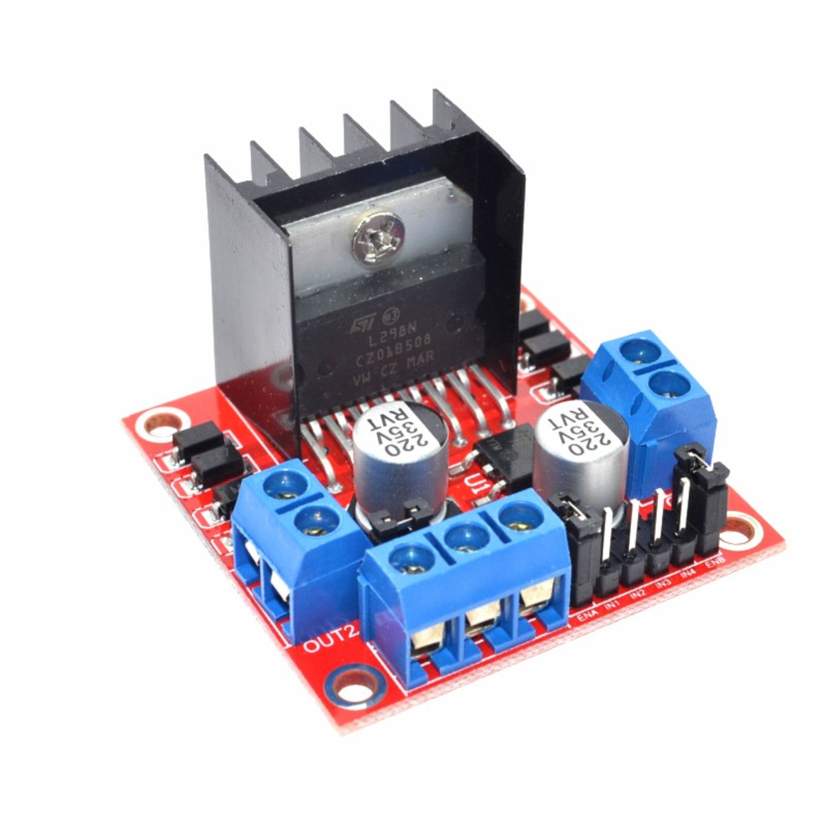
The L298N Dual H-Bridge Motor Driver Module lets you control the speed and direction of up to two DC motors — or one 2-phase stepper motor — from any Arduino or microcontroller. With a motor supply range of 5V to 35V and up to 2A per channel, it's the go-to driver for robotics, motorized projects, and DIY automation.
The module uses an H-bridge circuit to reverse motor polarity on the fly, giving you full forward/reverse control. Add PWM signals to the enable pins and you've got smooth, variable speed control too. An onboard 5V regulator (jumper-selectable) simplifies wiring by powering your Arduino directly from the motor supply — no separate logic power needed for supplies up to 12V.
⚠️ Important: If your motor supply voltage exceeds 12V, you must remove the 5V regulator jumper and provide a separate 5V supply to the +5V pin. Voltages over 12V will damage the onboard regulator. The module has an internal voltage drop of approximately 2V — plan your supply voltage accordingly.
⭐ Key Features
- Dual H-Bridge Driver — Control two DC motors independently or one bipolar stepper motor
- Wide Voltage Range — Motor supply from 5V to 35V DC
- 2A Per Channel — Up to 2A peak current per motor output
- PWM Speed Control — Variable speed via PWM on the ENA/ENB enable pins
- Direction Control — Simple HIGH/LOW logic on IN1–IN4 pins for forward, reverse, and stop
- Onboard 5V Regulator — Jumper-selectable; powers your Arduino from the motor supply (6–12V input)
- Screw Terminals — Secure connections for motors and power supply
- Built-in Flyback Diodes — Protects against voltage spikes from inductive motor loads
- TTL Compatible — Standard 5V logic level inputs work directly with Arduino and most microcontrollers
📊 Specifications
| Driver Chip | L298N Dual H-Bridge |
| Motor Supply Voltage (Vcc) | +5V to +35V DC |
| Logic Voltage (Vss) | +4V to +5.5V DC (not required when onboard regulator is enabled) |
| Peak Output Current | 2A per channel |
| Control Signal Input | 4.5–5.5V (HIGH), 0V (LOW) |
| Maximum Power Consumption | 20W |
| Internal Voltage Drop | ~2V |
| Onboard 5V Regulator | Yes (jumper-selectable; input must be 6–12V when enabled) |
| Motor Outputs | 2 channels via screw terminals |
| Control Inputs | IN1, IN2, IN3, IN4, ENA, ENB |
| Operating Temperature | −25°C to +130°C |
| Dimensions | Approx. 43 × 43 × 27 mm (1.7 x 1.7 x 1.1 inches) L × W × H |
| Weight | ~26g |
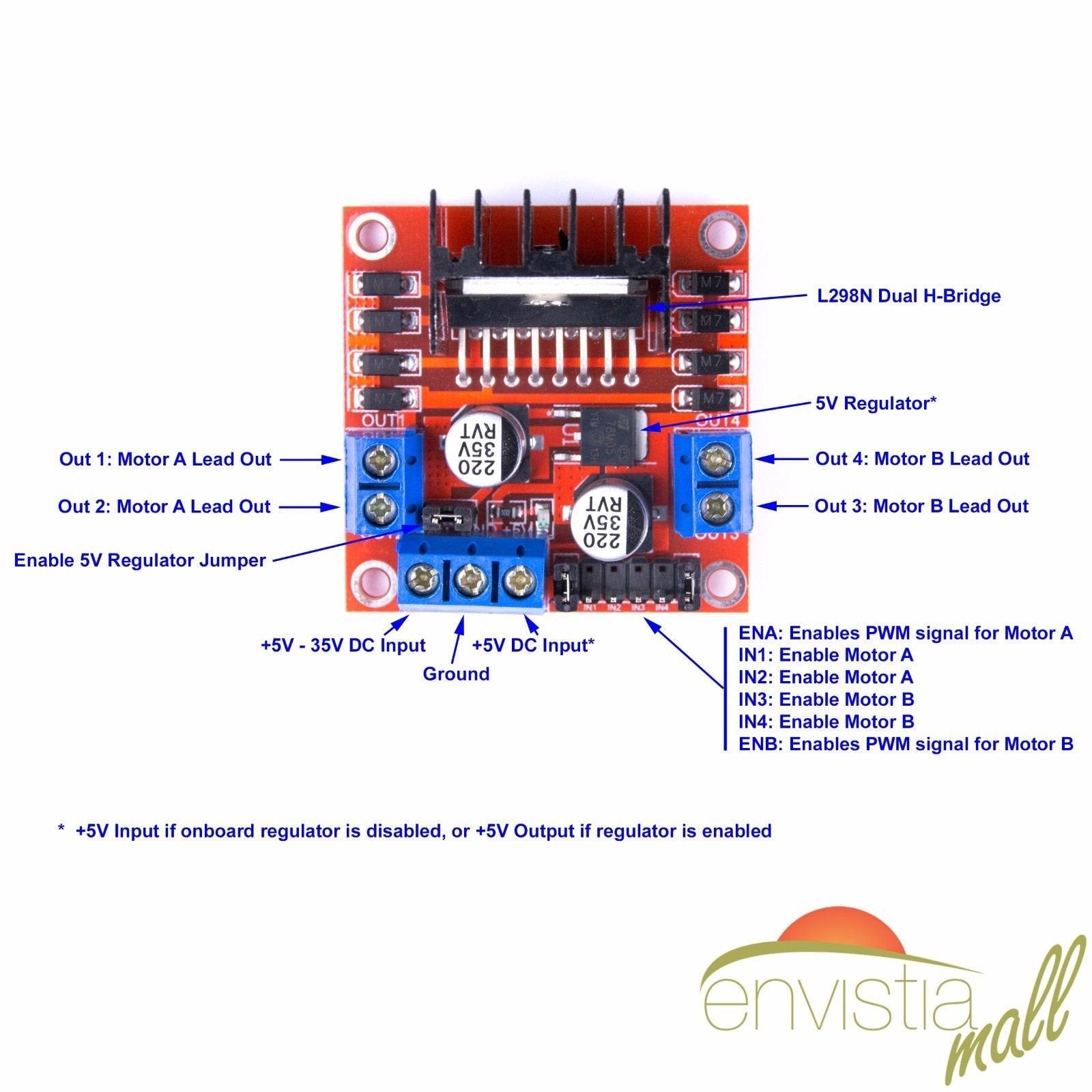
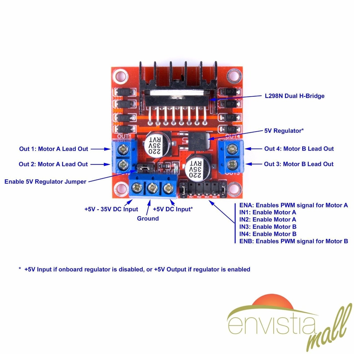
📌 Pinout
| Pin / Terminal | Function |
|---|---|
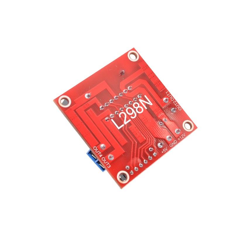
| +12V (Vcc) | Motor power supply input (+5V to +35V). Must be at least 6V when regulator is enabled. |
| GND | Common ground — connect to Arduino GND and motor supply ground. |
| +5V | OUTPUT when regulator jumper installed (powers Arduino); INPUT when jumper removed (supply 5V for logic). |
| OUT1 / OUT2 | Motor A output terminals. |
| OUT3 / OUT4 | Motor B output terminals. |
| ENA | Enable Motor A. Jumper = full speed. PWM input = variable speed. GND = disabled. |
| IN1 | Direction control input 1 for Motor A. |
| IN2 | Direction control input 2 for Motor A. |
| IN3 | Direction control input 1 for Motor B. |
| IN4 | Direction control input 2 for Motor B. |
| ENB | Enable Motor B. Functions the same as ENA. |
🔧 Motor Direction Control
The direction of each motor is controlled by the logic state of the IN pins:
Motor A (IN1 / IN2)
| IN1 | IN2 | Action |
|---|---|---|
| HIGH | LOW | Forward (direction 1) |
| LOW | HIGH | Backward (direction 2) |
| LOW | LOW | Stop (coast) |
| HIGH | HIGH | Stop (brake) |
Motor B (IN3 / IN4)
| IN3 | IN4 | Action |
|---|---|---|
| HIGH | LOW | Forward (direction 1) |
| LOW | HIGH | Backward (direction 2) |
| LOW | LOW | Stop (coast) |
| HIGH | HIGH | Stop (brake) |
🔋 Power Configuration
Option 1: Regulator Enabled (Jumper Installed)
- Connect motor power supply (6V to 12V) to the +12V and GND terminals.
- The +5V pin becomes an OUTPUT — use it to power your Arduino.
- No separate 5V supply needed for logic circuitry.
Option 2: Regulator Disabled (Jumper Removed)
- Required when motor supply exceeds 12V (up to 35V max).
- Connect motor power supply to the +12V and GND terminals.
- The +5V pin becomes an INPUT — you must supply 5V here for logic circuitry.
🚀 Getting Started
- Connect your motor power supply (6–12V) to the +12V and GND screw terminals.
- Connect Motor A to OUT1/OUT2 and/or Motor B to OUT3/OUT4.
- Wire IN1, IN2 (and IN3, IN4 for Motor B) to Arduino digital pins.
- Remove the ENA/ENB jumpers and wire them to Arduino PWM pins for speed control (or leave jumpers installed for full speed).
- Connect the module GND to Arduino GND. If the regulator jumper is installed, connect +5V to Arduino 5V.
- Upload your sketch and control your motors.
💡 Tip: See our complete User Guide linked below for detailed wiring diagrams, pinout tables, sample code for DC motors and stepper motors, and troubleshooting tips.
🔌 Compatible With
- Arduino Uno, Mega, Nano, and other Arduino boards
- ESP32 and ESP8266 (with 5V logic level shifting)
- Raspberry Pi (with 5V logic level shifting)
- STM32, Teensy, and other 5V-compatible microcontrollers
- DC motors (5V–35V, up to 2A per channel)
- Bipolar stepper motors (4-wire, 2-phase)
🎯 Applications
- Two-wheel and four-wheel drive robots
- Motorized camera sliders and pan/tilt mechanisms
- Conveyor belt systems and automated feeders
- Automated blinds and curtain controllers
- Basic CNC and 3D printer stepper control
- PWM-controlled high-power LED arrays
- Science fair and educational motor control projects
📦 What's in the Box
- 1x L298N Dual H-Bridge Motor Driver Module
Motors, power supply, Arduino, and jumper wires are not included.
🛒 What You'll Need
- Arduino or microcontroller — to send control signals (direction and PWM speed)
- DC power supply — 6V to 35V, rated for your motor's current draw
- DC motors or stepper motor — compatible with the module's voltage and current ratings
- Jumper wires — for connecting control pins to your Arduino
- Small flathead screwdriver — for the screw terminals
⚠️ Important Notes
- Do not exceed 35V on the +12V motor supply terminal.
- Do not exceed 2A continuous current per motor channel.
- If motor supply voltage exceeds 12V, remove the 5V regulator jumper and provide an external 5V supply.
- The ~2V internal voltage drop means motors receive less voltage than the supply. Plan accordingly.
- Always connect a common ground between the Arduino, the L298N module, and the motor power supply.
- The L298N chip will get warm under load — this is normal. A heatsink is included on the module.
📄 Documentation & Resources
- User Guide — Detailed wiring, code examples, and troubleshooting for this module
- All Motor Driver & Controller User Guides — Browse the User Guides for our full selection of motor driver modules
Sold and supported by Envistia Mall. Ships from the USA. For wiring diagrams and troubleshooting, see the User Guide. The manufacturer and Envistia LLC (dba Envistia Mall) are not responsible for any damages or losses resulting from the use of this product. Always follow proper electrical safety practices when working with electronic components. Specifications are based on manufacturer data and are subject to change without notice.
Share


used a pair to control 4 robotic car wheels. worked as expected.
Worked as expected. I used these for both a Stepper motor driver and to drive a DC gear motor.