


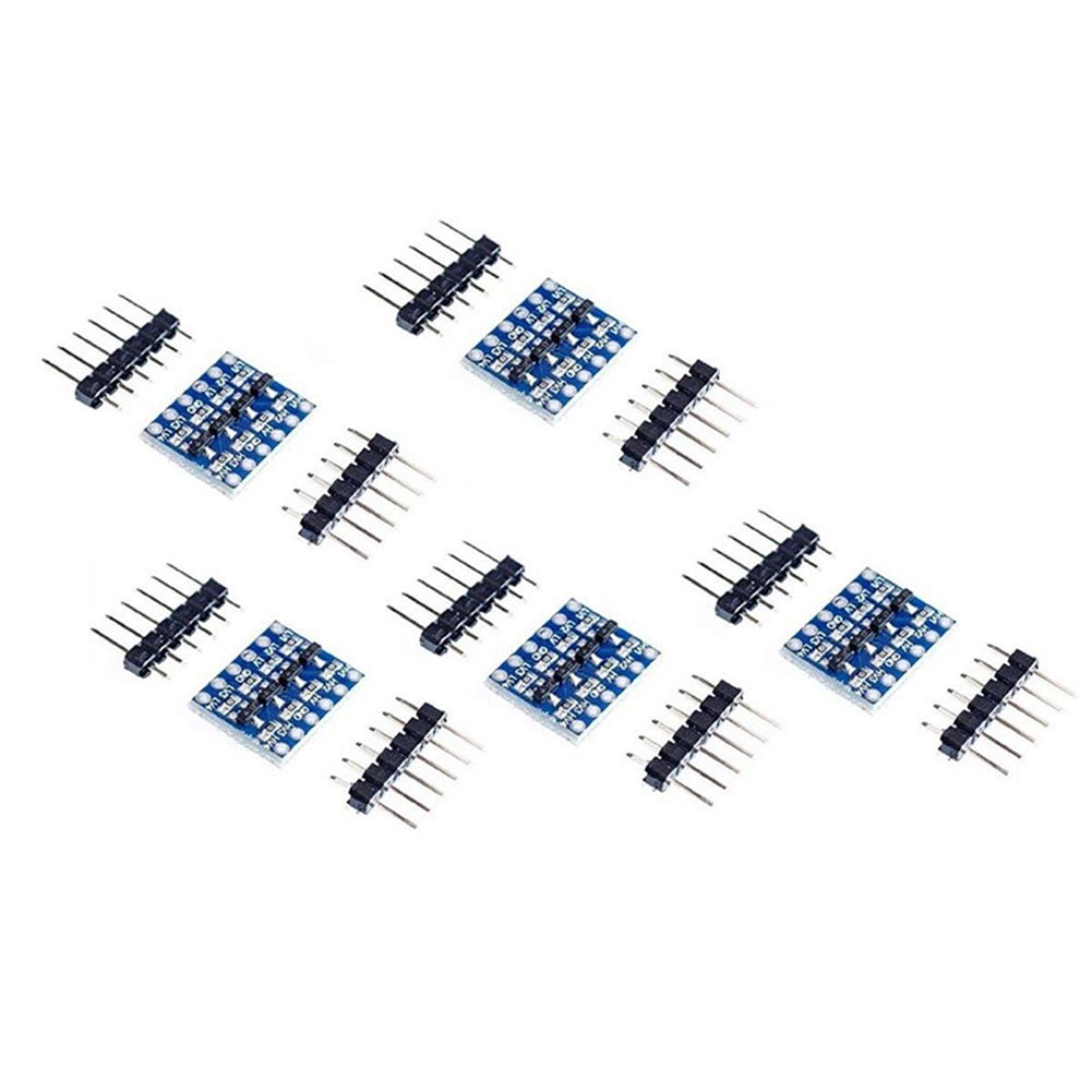
Bi-Directional 5V to 3.3V 4-Channel Logic Level Converter Module for I2C & Arduino 1/5 Piece Pkgs
Bi-Directional 5V to 3.3V 4-Channel Logic Level Converter Module for I2C & Arduino 1/5 Piece Pkgs
Couldn't load pickup availability
📋 Overview
Trying to connect a 3.3V sensor or I2C module to a 5V Arduino? This compact bi-directional logic level converter is the solution. It safely translates digital signals between 5V and 3.3V — in both directions, simultaneously, on the same channel — so you can mix voltage levels in your project without risking damage to sensitive components.
With four independent channels and automatic direction detection (no direction-control pin needed), this module works seamlessly with I2C buses, SPI signals, and general-purpose digital lines. It's compatible with 1.8V, 2.8V, 3.3V, and 5V logic, making it one of the most versatile level-shifting tools you can have on your bench.
⭐ Key Features
- Bi-Directional Conversion — Shifts signals from 5V down to 3.3V AND from 3.3V up to 5V on the same channel, automatically.
- 4 Independent Channels — Convert up to four digital signal lines simultaneously (HV1–HV4 paired with LV1–LV4).
- Wide Voltage Compatibility — Works with 1.8V, 2.8V, 3.3V, and 5V logic devices.
- I2C & Arduino Ready — Designed specifically for I2C bus signals (SDA and SCL) but works with any digital signal.
- Auto Direction Detection — MOSFET-based design automatically handles signal direction with no manual control needed.
- Compact & Breadboard Friendly — Small form factor with included pin headers for fast, tool-free prototyping.
- Component Protection — Prevents 5V signals from reaching 3.3V devices, protecting components from voltage damage.
🎯 Applications
- Connecting 3.3V I2C sensors (temperature, humidity, pressure, IMU) to a 5V Arduino
- Interfacing 3.3V OLED or LCD displays with 5V microcontrollers
- Level-shifting SPI signals (MOSI, MISO, SCK, CS) between 5V and 3.3V systems
- Bridging 5V Arduino GPIO with 3.3V Raspberry Pi or other single-board computers
- General-purpose digital signal conversion in mixed-voltage embedded systems
- Breadboard and prototype development requiring multiple simultaneous signal translations
📊 Specifications
| Parameter | Value |
|---|---|
| Number of Channels | 4 (independent) |
| Maximum High Voltage (HV) | 6V |
| Minimum Low Voltage (LV) | 1.8V |
| Supported Logic Levels | 1.8V, 2.8V, 3.3V, 5V |
| Signal Type | Digital only (not for analog signals) |
| Direction Control | Automatic — no manual control pin required |
| I2C Compatible | Yes (Standard Mode 100 kHz, Fast Mode 400 kHz) |
| Dimensions | Approx. 15 × 13 mm (0.6 × 0.5 inches) L × W |
| Package Includes | 1x or 5x module(s) + 2x pin headers per module |
📌 Pinout / Pin Diagram
The module has two parallel rows of pins — one row for the high-voltage side and one for the low-voltage side. Each numbered channel (1–4) pairs one HV pin with one LV pin.
High Voltage Side (HV)
| Pin | Description |
|---|---|
| HV | High voltage power input — connect to your 5V supply |
| GND | Common ground — must be shared with the LV system ground |
| HV1 – HV4 | Channel signal pins for the high-voltage side (5V logic) |
Low Voltage Side (LV)
| Pin | Description |
|---|---|
| LV | Low voltage power input — connect to your 3.3V supply |
| GND | Common ground — must be shared with the HV system ground |
| LV1 – LV4 | Channel signal pins for the low-voltage side (3.3V logic) |
Channel pairing: HV1 and LV1 form Channel 1, HV2 and LV2 form Channel 2, and so on. A signal on HV1 is shifted down and appears on LV1; a signal on LV1 is shifted up and appears on HV1. The module handles direction automatically.
🔌 Wiring / Connections
Power Connections
- Connect HV to your 5V supply (e.g., Arduino 5V pin).
- Connect LV to your 3.3V supply (e.g., Arduino 3.3V pin or sensor 3.3V rail).
- Connect both GND pins to the common ground shared by your 5V and 3.3V systems.
Signal Connections
- Connect the 5V device's signal line to the appropriate HVx pin.
- Connect the 3.3V device's corresponding signal line to the matching LVx pin.
- Use as many or as few channels as your project needs — unused channels can be left unconnected.
I2C Example — Arduino to 3.3V Sensor
| Arduino (5V) | Level Converter — HV Side | Level Converter — LV Side | 3.3V Sensor |
|---|---|---|---|
| 5V | HV | LV | 3.3V |
| GND | GND | GND | GND |
| SDA (A4) | HV1 | LV1 | SDA |
| SCL (A5) | HV2 | LV2 | SCL |
Arduino I2C pin reference: SDA and SCL are on pins A4/A5 (Uno & Nano) and pins 20/21 (Mega).
⚠️ Important Notes
- Digital signals only. This module is not suitable for analog voltage translation. For analog signals, use a resistor voltage divider instead.
- Common ground required. Both your 5V and 3.3V systems must share a common ground. Without it, the converter will not function correctly.
- HV must not exceed 6V. Applying more than 6V to the HV pin may damage the module.
- LV must be at least 1.8V. The low-voltage side requires a minimum of 1.8V to operate the MOSFET circuitry.
- I2C pull-up resistors. I2C communication requires pull-up resistors on SDA and SCL. Many sensor breakout boards include them; verify pull-ups are present on both sides of the bus if you experience communication issues.
📦 What's in the Box
- 1x or 5x Bi-Directional 5V to 3.3V 4-Channel Logic Level Converter Module (quantity selected above)
- 2x Pin headers per module (for soldering to the board)
📄 Documentation & Resources
- Bi-Directional 5V to 3.3V Logic Level Converter User Guide — Full pinout, wiring diagrams, Arduino I2C example code, and troubleshooting steps.
-
All Logic & Timing Module User Guides
Sold and supported by Envistia Mall. Ships from the USA. For complete setup instructions, wiring, and troubleshooting, visit the User Guide linked above. The manufacturer and Envistia LLC (dba Envistia Mall) are not responsible for any damages or losses resulting from the use of this product. Always follow proper electrical safety practices when working with electronic components. Specifications are based on manufacturer data and are subject to change without notice.
Share


This module is very small, and challenging to solder to. It works fine however.
The product is amazing, I got what was expected and it saved alot of time. I’ll recommend this product to everyone looking to use. The only reason to give 4 stars instead of 5 is because the packaging has a area to improve.
Good quality little board I will use on some breadboard projects programmed from my pi.
Tiny! I love it, worked great for my leds, proof that size doesn't matter.