20mA LED Driver Constant Current Source Regulator - Packs of 1/2/5/10 Drivers
20mA LED Driver Constant Current Source Regulator - Packs of 1/2/5/10 Drivers
Couldn't load pickup availability
📋 Overview
The Envistia 20mA LED Driver is a constant current regulator (CCR) module that delivers a steady 20mA to your LEDs — no resistor calculations required. Simply wire it in series with your LEDs and it automatically maintains a constant 20mA regardless of supply voltage changes. Think of it as a smart, self-adjusting resistor that keeps your LEDs at consistent brightness whether you're running from a 5V USB supply, a 12V car battery, or a 24V industrial system.
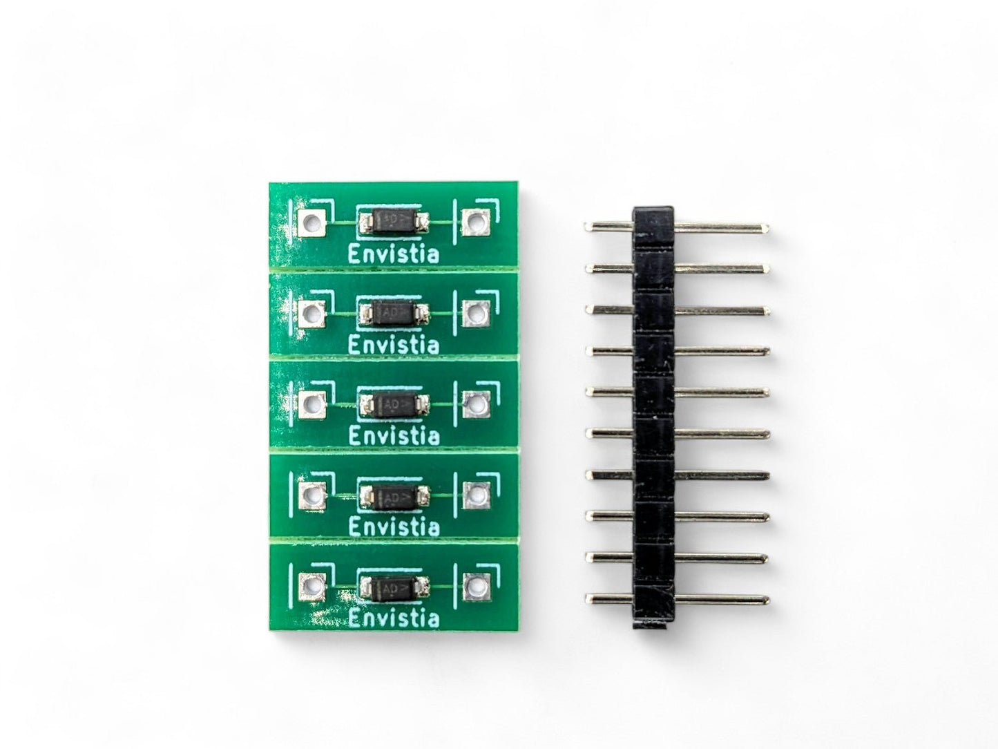
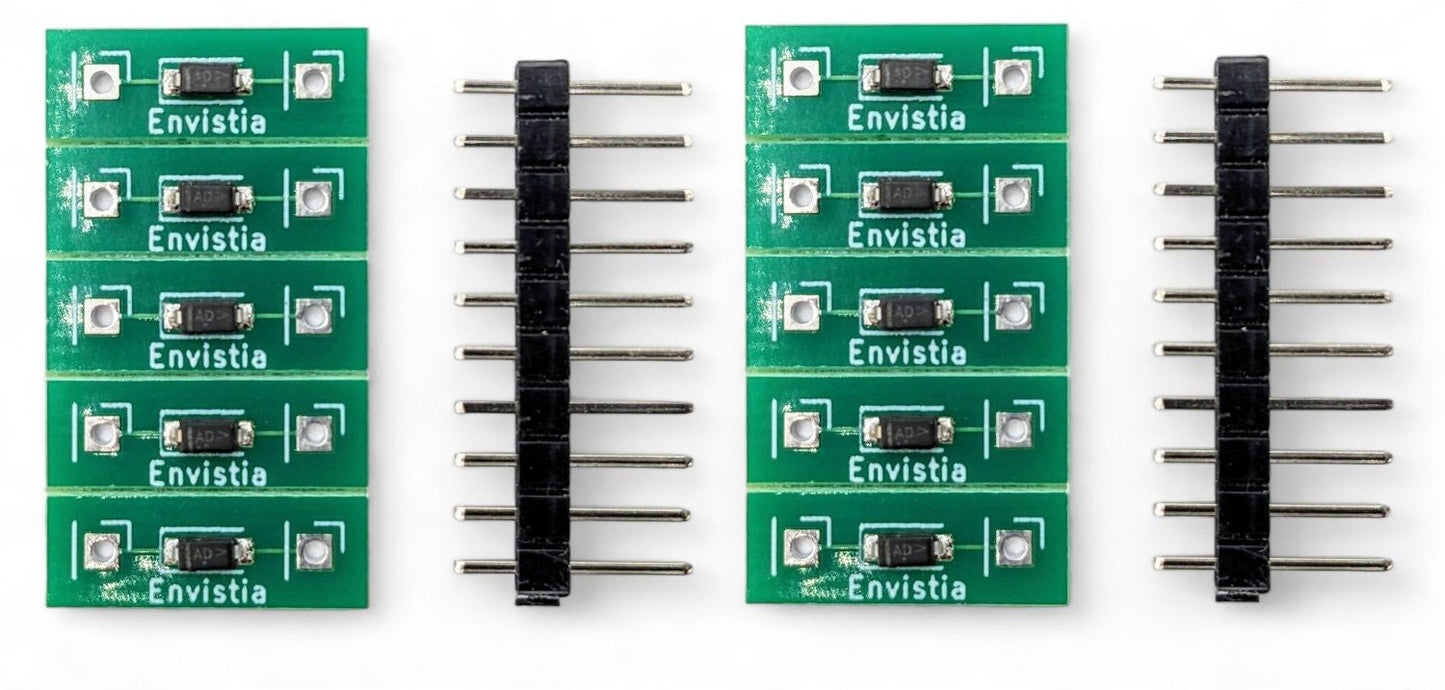
Unlike bare surface-mount components sold by other suppliers, the Envistia driver is mounted on a PCB module with through-hole pins spaced at 0.4 inches (10.16mm), making it easy to solder into a circuit or plug directly into a standard breadboard. Multiple modules are provided on a scored circuit board that snaps apart by hand.
⭐ Key Features
- Constant 20mA Output — Delivers a regulated 20mA (±2mA) regardless of input voltage, eliminating the need for current-limiting resistors
- Tight ±2mA Tolerance — Tighter than the ±3mA offered by many competing products, ensuring more consistent LED brightness across multiple circuits
- Wide Voltage Range — Operates from 2V to 45V DC across the module (recommended maximum 20V for long-term reliability)
- No Calculations Required — Drop-in replacement for current-limiting resistors; no need to calculate values for different LED and voltage combinations
- Voltage Fluctuation Immunity — Automatically compensates for voltage changes, perfect for automotive (11V–14.5V) and solar systems
- Series LED Support — Drive multiple LEDs in series with a single module, as long as the voltage overhead requirement is met
- Parallel Stacking — Wire multiple modules in parallel for higher current (40mA, 60mA, etc.)
- Breadboard and PCB Friendly — Through-hole pins with 0.4-inch (10.16mm) spacing fit standard breadboards and are easy to solder
- PCB Module Format — Mounted on a PCB for easier handling and soldering compared to bare surface-mount components
- Scored Panel — Modules snap apart easily from the scored circuit board
📊 Specifications
| Output Current | 20mA ±2mA |
| Input Voltage (Vak) | 2V to 45V DC (across the module) |
| Recommended Maximum Voltage | 20V (across the module) * |
| Voltage Overhead (Dropout) | ~1.8V minimum |
| Module Dimensions (excluding pins) | Approx. 15.75 × 5.6 × 2.8 mm (0.62 × 0.22 × 0.11 inches) L × W × H |
| Pin-to-Pin Spacing | 10.16 mm (0.4 inches) |
| Pin Type | Through-hole |
| Form Factor | PCB module on scored panel |
| Power Source | DC only |
* Note on Maximum Voltage: While the driver IC is rated for up to 45V, we recommend a maximum of 20V across the module for long-term reliability. At higher voltages, the module must dissipate more power as heat, which reduces its lifespan. For most LED applications — including 12V automotive — you'll be well within this recommended range.
🔧 How It Works
The driver is a two-terminal constant current source that behaves like a self-adjusting resistor. Wire it in series with your LED(s), apply DC voltage, and the driver automatically regulates the current to 20mA. If the supply voltage changes — for example, a car battery swinging from 11V to 14.5V — the driver absorbs the difference and keeps the current (and your LED brightness) constant.
The driver needs a minimum of approximately 1.8V across itself (the "overhead" or "dropout" voltage) to regulate properly. Your minimum supply voltage must be:
Minimum Supply Voltage = Total LED Forward Voltage(s) + 1.8V
🔌 Wiring
The module is polarity-sensitive — check the PCB markings for correct orientation before wiring. It can be placed anywhere in the series loop (before, after, or between LEDs) as long as polarity is correct.
Basic Single-LED Circuit
(+) Power Supply ──── Anode(+) LED Cathode(-) ──── Driver Module ──── (-) Power Supply
Multiple LEDs in Series
(+) Power Supply ── LED1 ── LED2 ── LED3 ── Driver Module ── (-) Power Supply
Parallel Modules for Higher Current
                    ┌── Driver Module 1 ──┐
(+) Supply ── LED ──┤                     ├── (-) Supply
                    └── Driver Module 2 ──┘

Result: 20mA + 20mA = 40mA through the LED
⚠️ Important: Reversed polarity can damage both the driver module and your LEDs. If your LEDs don't light up, the first thing to check is whether the driver module is oriented correctly.
🔋 Series LED Quick Reference
The number of LEDs you can drive in series depends on your supply voltage. Add up the forward voltages of all LEDs, then add the 1.8V overhead:
| Supply Voltage | LED Type (Typical Vf) | Max LEDs in Series | Calculation |
|---|---|---|---|
| 5V | Red (2.0V) | 1 | 2.0 + 1.8 = 3.8V needed |
| 9V | Red (2.0V) | 3 | (3 × 2.0) + 1.8 = 7.8V needed |
| 12V | Red (2.0V) | 5 | (5 × 2.0) + 1.8 = 11.8V needed |
| 12V | White (3.2V) | 3 | (3 × 3.2) + 1.8 = 11.4V needed |
| 12V | Blue (3.2V) | 3 | (3 × 3.2) + 1.8 = 11.4V needed |
| 12V | Green (3.0V) | 3 | (3 × 3.0) + 1.8 = 10.8V needed |
| 24V | White (3.2V) | 6 | (6 × 3.2) + 1.8 = 21.0V needed |
💡 Tip: For 12V automotive systems, design for a minimum supply voltage of 11V (engine cranking). For best efficiency, maximize the number of series LEDs to reduce the voltage the driver must dissipate as heat.
🎯 Typical Applications
- 12V Automotive LED Lighting — Dash indicators, accent lighting, interior lights, and custom LED installations. The driver handles 11V–14.5V voltage swings automatically.
- Model Railroad and Scale Models — Consistent LED lighting for buildings, signals, and rolling stock from variable DC supplies
- LED Indicator Circuits — Status indicators on custom electronics, control panels, and enclosures
- Hobby and Maker Projects — Arduino, Raspberry Pi, and breadboard projects with various voltage sources
- Marine and RV Lighting — 12V LED installations where battery voltage fluctuates
- Solar-Powered LED Systems — LED lighting from solar battery banks with varying charge states
- Resistor Replacement — Drop-in replacement for current-limiting resistors in any 20mA LED circuit
📦 What's in the Box
- 20mA LED Driver CCR Module(s) on scored circuit board (quantity per your selected option)
- Header Pins - 2 per LED Driver
🚀 Getting Started
- Snap a module from the scored panel by gently bending along the score line
- Check the polarity markings on the PCB — the module must be wired in the correct orientation
- Wire in series with your LED(s) — the module can go before, after, or between LEDs
- Apply DC voltage — ensure your supply voltage exceeds the total LED forward voltage plus 1.8V overhead
- Verify operation — your LED(s) should light at consistent brightness
💡 Tip: The 0.4-inch pin spacing fits standard breadboards, so you can prototype your circuit before committing to solder. See our User Guide for detailed wiring diagrams, automotive configurations, power dissipation calculations, and troubleshooting.
⚠️ Important Notes
- Polarity-sensitive. The driver module must be wired in the correct orientation. Reversed polarity can damage the module and your LEDs.
- DC only. This module is designed for DC circuits only. Do not use with AC power.
- Not a voltage regulator. This module regulates current, not voltage. It limits current to 20mA — it does not convert or step down voltage.
- Recommended maximum 20V across the module. While the IC is rated for 45V, we recommend 20V maximum for long-term reliability and reduced heat.
- Not for high-power LEDs. This driver provides 20mA for standard indicator LEDs (3mm, 5mm, SMD). High-power LEDs (1W, 3W, 5W) require a different type of driver.
- One driver per series string. Each series string needs only one driver. Do not place multiple drivers in series — use parallel for more current.
📄 Documentation & Resources
- 20mA LED Driver User Guide — Wiring diagrams, automotive configurations, power dissipation, and troubleshooting
- Browse All Laser, LED and LED Accessory User Guides
Sold and supported by Envistia Mall. Ships from the USA. For wiring diagrams and troubleshooting, see the User Guide. The manufacturer and Envistia LLC (dba Envistia Mall) are not responsible for any damages or losses resulting from the use of this product. Always follow proper electrical safety practices when working with electronic components. Specifications are based on manufacturer data and are subject to change without notice.
Share