Mini360 Ultra-Small 1-15V Output DC-DC Step-Down Buck Converter Module for RCs, Quadcopters, Drones
Mini360 Ultra-Small 1-15V Output DC-DC Step-Down Buck Converter Module for RCs, Quadcopters, Drones
Couldn't load pickup availability
📋 Overview
The Mini360 is an ultra-miniature DC-DC step-down (buck) voltage regulator module built around the MPS MP1482DS synchronous rectifier IC. It accepts an input voltage of 4.75V to 18V and provides an adjustable output from 1.0V to 15V, set via a small onboard potentiometer. At just 0.67 x 0.43 x 0.16 inches (17 × 11 × 4 mm) and weighing only 0.04 ounces (1 gram), it's one of the smallest buck converter modules available — purpose-built for weight- and space-critical applications like RC airplanes, quadcopters, drones, and compact DIY electronics.
The synchronous rectification design delivers up to 96% conversion efficiency, meaning very little energy is wasted as heat — a massive improvement over linear regulators like the 7805. Whether you need to step down a 2S/3S LiPo battery to 5V for a flight controller, or convert a 12V supply to 3.3V for a sensor, the Mini360 gets the job done in a tiny footprint with no software or programming required.
⚠️ Important: This is a step-down (buck) converter only — the output voltage must always be set lower than the input voltage. Always set and verify the output voltage with a multimeter before connecting your load. Maximum continuous output current is 1.8A.
⭐ Key Features
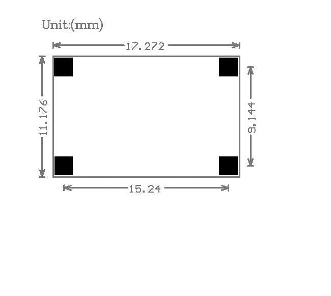
- Ultra-Small Form Factor — Just 17 × 11 × 4 mm and 1 gram, ideal for weight- and space-sensitive builds like drones and RC aircraft
- Wide Input Range — Accepts 4.75V to 18V DC input, compatible with 2S through 4S LiPo batteries and common DC adapters
- Adjustable Output — 1.0V to 15V DC, easily set with the onboard potentiometer
- High Efficiency — Up to 96% conversion efficiency thanks to synchronous rectification, far superior to linear regulators
- 1.8A Continuous / 2A Peak — Handles most low-power loads with headroom for brief current surges
- Low Output Ripple — 30mV at no load for clean, stable power delivery
- Built-In Thermal Protection — 160°C thermal shutdown protects the IC from overheating
- Wide Temperature Range — Operates from -40°C to +85°C
- No Software Required — Pure hardware solution; just wire it up and adjust the trimpot
📊 Specifications
| Regulator IC | MPS MP1482DS |
| Module Type | Non-isolated synchronous buck (step-down) regulator |
| Input Voltage | DC 4.75V – 18V |
| Output Voltage | DC 1.0V – 15V (adjustable via potentiometer) |
| Output Current | 1.8A continuous, 2A peak/surge |
| Conversion Efficiency | Up to 96% |
| Switching Frequency | 340 KHz |
| Output Ripple | 30mV (no-load) |
| Load Regulation | ± 0.5% |
| Voltage Regulation | ± 2.5% |
| Thermal Shutdown | 160°C (built-in) |
| Operating Temperature | -40°C to +85°C |
| Dimensions | Approx. 17 × 11 × 4 mm (0.67 x 0.43 x 0.16 inches) L × W × H |
| Weight | 1 gram (0.04 ounces) |
📌 Pinout / Pad Layout
The Mini360 has four solder pads — two for input and two for output. Pad labels are printed on the reverse (bottom) side of the board.
| IN+ | Positive DC input (4.75V – 18V) |
| IN− | Negative DC input (Ground) |
| OUT+ | Positive DC output (1.0V – 15V, adjusted by trimpot) |
| OUT− | Negative DC output (Ground) |
The onboard potentiometer (trimpot) on the top side of the board adjusts the output voltage. A small Phillips or flathead screwdriver is needed to turn it.
🔌 Wiring / Connections
The Mini360 uses solder pads rather than screw terminals or pin headers. Soldering is required.
- Solder your power source's positive (+) wire to the IN+ pad
- Solder your power source's negative (−) wire to the IN− pad
- Solder your load's positive (+) wire to the OUT+ pad
- Solder your load's negative (−) wire to the OUT− pad
🚀 Getting Started
Step 1: Set the Output Voltage (Before Connecting Your Load)
- Connect your input power source (4.75V–18V) to the IN+ and IN− pads
- With no load connected, use a multimeter set to DC voltage across the OUT+ and OUT− pads
- Use a small screwdriver to turn the onboard potentiometer until the multimeter reads your desired output voltage
- Turning the potentiometer clockwise typically increases the voltage; counterclockwise decreases it
Step 2: Connect Your Load
- Disconnect the input power
- Solder your load wires to the OUT+ and OUT− pads
- Reconnect the input power
- Verify the output voltage again under load — it may shift slightly and need a minor trimpot adjustment
⚠️ Important: Always set and verify the output voltage with a multimeter before connecting your load. The potentiometer may be set to any arbitrary voltage from the factory. Never assume the output is safe for your load without measuring it first.
🎯 Typical Applications
- RC Aircraft & Drones — Step down 2S/3S/4S LiPo battery voltage to 5V for flight controllers, receivers, or servos
- Quadcopters — Power FPV cameras, video transmitters, or GPS modules from the main battery
- Arduino & Microcontroller Projects — Provide a regulated 5V or 3.3V supply from a higher-voltage battery or adapter
- Raspberry Pi — Power a Pi from a 12V source (set output to 5.1V)
- LED Projects — Step down voltage for LED strips or individual LEDs
- Portable Electronics — Regulate battery voltage for custom handheld devices
- Replacing Linear Regulators — Drop-in efficiency upgrade over 7805 or similar linear regulators
- Sensor Power — Provide clean, regulated power to sensors in remote or embedded systems
⚠️ Important Notes
- Step-down only. The output voltage must always be lower than the input voltage. This module cannot boost (step up) voltage.
- No reverse polarity protection. Connecting the input with reversed polarity will damage the module.
- Output voltage is not factory-set. The potentiometer may be at any arbitrary position when you receive the module. Always measure before connecting a load.
- 1.8A continuous maximum. The 2A rating is for peak/surge only. Sustained loads should stay at or below 1.8A.
- Efficiency varies with conditions. The 96% figure is a maximum under ideal conditions. Larger voltage differentials and higher currents reduce efficiency.
- No enable/disable pin. The module is always active when input power is applied.
- Solder pads only. There are no screw terminals, pin headers, or connectors. Soldering is required.
- Maintain voltage headroom. Keep the input voltage at least 1V–2V above your desired output for best regulation.
📦 What's in the Box
- 1x Mini360 DC-DC Step-Down Buck Converter Module
📄 Documentation & Resources
- User Guide — Wiring, Voltage Adjustment, Applications & Troubleshooting
- All Buck Converter Module User Guides
Sold and supported by Envistia Mall. Ships from the USA. For wiring diagrams, setup instructions, and troubleshooting, see the User Guide. The manufacturer and Envistia LLC (dba Envistia Mall) are not responsible for any damages or losses resulting from the use of this product. Always follow proper electrical safety practices when working with electronic components. Specifications are based on manufacturer data and are subject to change without notice.
Share