


NE555 Duty Cycle Adjustable Pulse Frequency Square Wave Signal Generator Module
NE555 Duty Cycle Adjustable Pulse Frequency Square Wave Signal Generator Module
Couldn't load pickup availability
📋 Overview
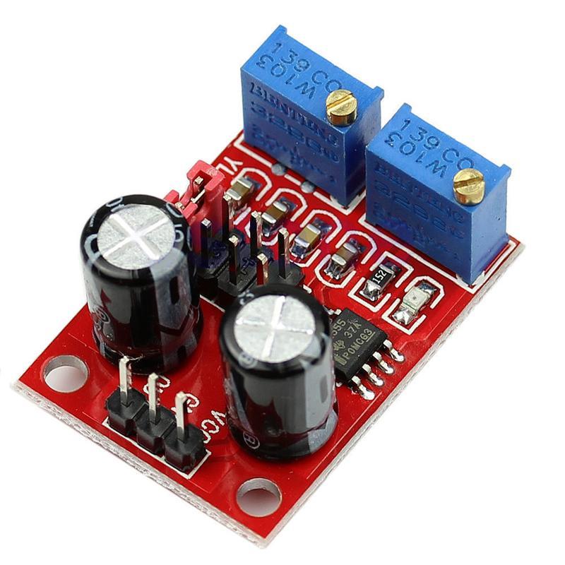
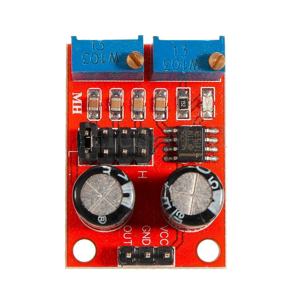
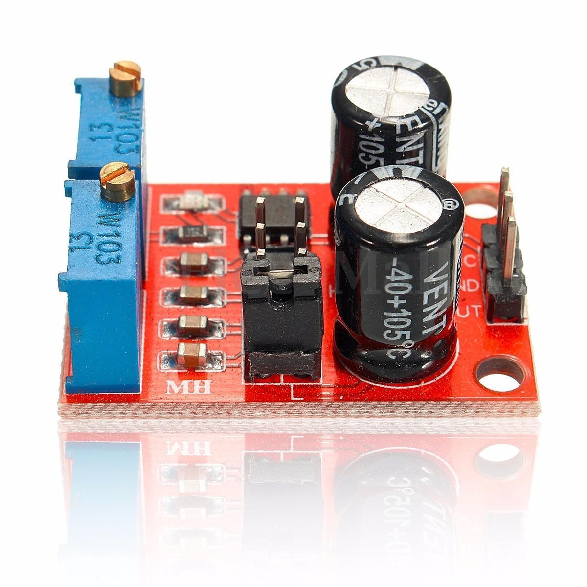
The NE555 Square Wave Pulse Generator Module is a compact, versatile signal generator based on the classic NE555 timer IC configured in astable (free-running) mode. It produces a continuous square wave output with adjustable frequency and duty cycle, making it ideal for driving stepper motors, generating clock signals for microcontrollers, testing circuits, and a wide range of prototyping applications.
The module features two multi-turn potentiometers (RA and RB) and a 4-position jumper block that together give you precise control over output frequency across four selectable ranges — from approximately 1 Hz to over 200 kHz. An onboard LED provides visual confirmation of the output signal. Just supply 5V to 15V DC, select your frequency range with the jumper, fine-tune with the pots, and you have a clean square wave output ready to go.
⭐ Key Features
- Wide Frequency Range: Adjustable output from approximately 1 Hz to over 200 kHz
- 4 Selectable Frequency Ranges: Jumper block selects the timing capacitor for coarse range selection
- Adjustable Duty Cycle: Two multi-turn potentiometers (RA and RB, 0–10 kΩ each) for fine control of frequency and duty cycle
- Flexible Input Voltage: Operates on 5V to 15V DC
- Square Wave Output: TTL-compatible at 5V VCC, suitable for driving motors, testing circuits, and generating clock pulses
- LED Indicator: Onboard LED flashes with the output signal for visual confirmation
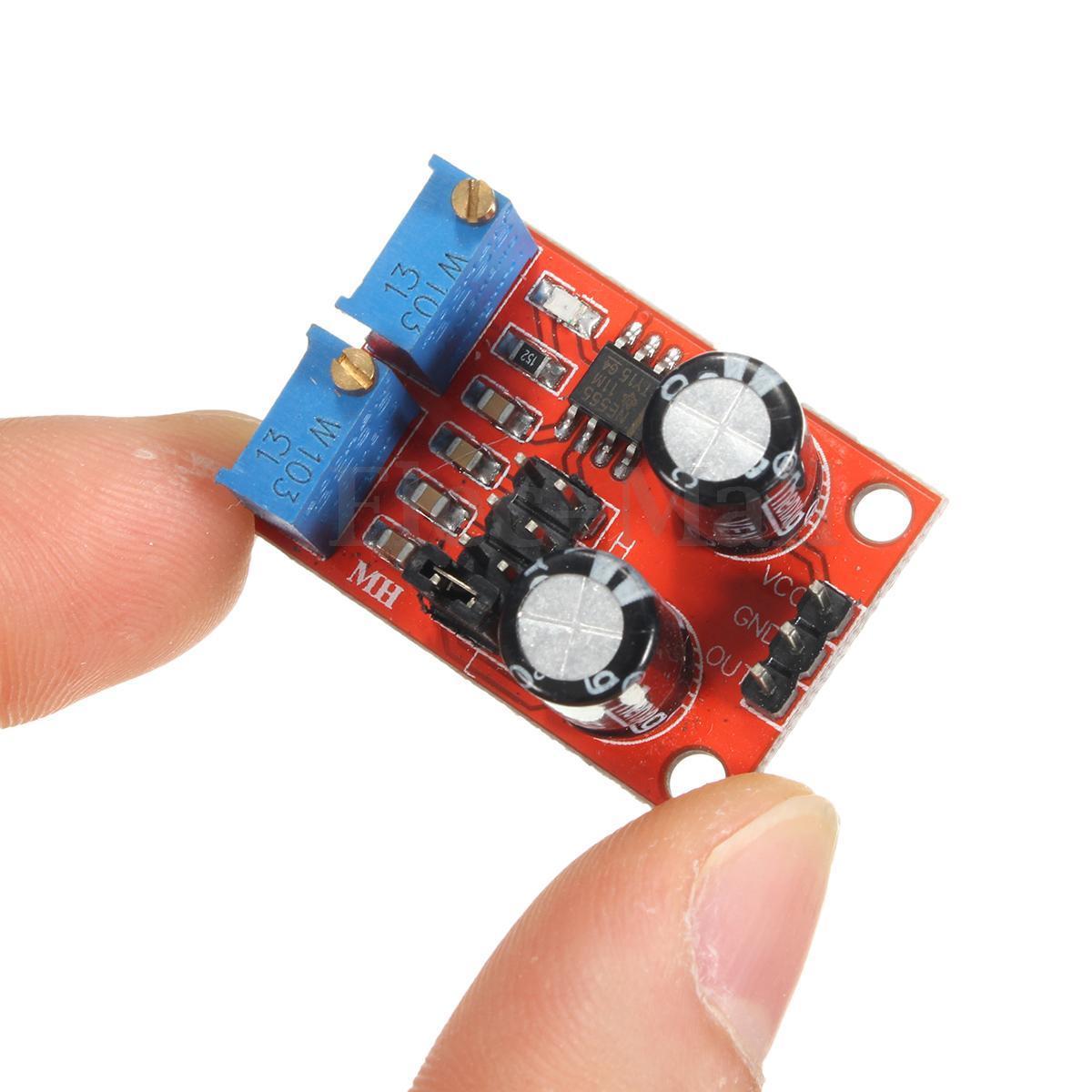
- Ultra-Compact Size: Measures just Approx. 31 × 22 mm (1.22 x 0.87 inches) L × W
- Simple 3-Pin Interface: VCC, GND, and OUT pins with standard 2.54mm header spacing
- Classic NE555 Timer IC: Proven, reliable timer used in countless electronics projects worldwide
📊 Specifications
| Parameter | Value |
|---|---|
| Main IC | NE555 Timer |
| Operating Mode | Astable (free-running) |
| Input Voltage (VCC) | 5V – 15V DC |
| Input Current | ~15 mA at 5V; ~35 mA at 12V |
| Output Signal | Square wave (TTL-compatible at 5V VCC) |
| Output Amplitude | ~4.2V peak-to-peak (at 5V VCC) to ~11.4V peak-to-peak (at 12V VCC) |
| Maximum Output Current | ~15 mA (VCC = 5V); ~35 mA (VCC = 12V) |
| Frequency Range | ~1 Hz to >200 kHz (jumper-selectable) |
| Potentiometers | 2× multi-turn (RA and RB), 0–10 kΩ each |
| Frequency Selection | 4-position jumper header (selects timing capacitor) |
| LED Indicator | Yes — flashes with output frequency |
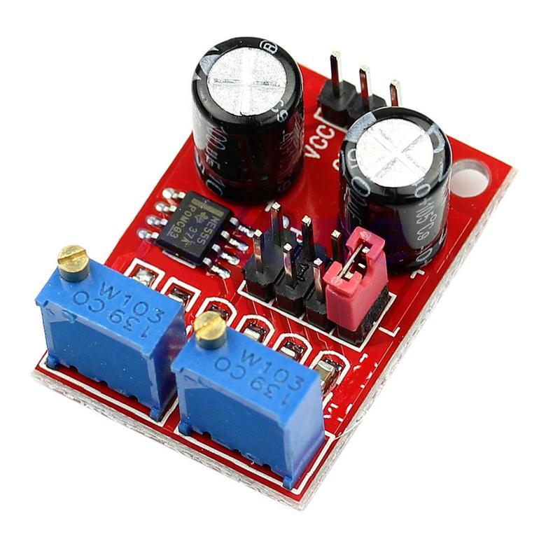
| Output Pins | VCC, GND, OUT (2.54mm header) |
| Board Dimensions | Approx. 31 × 22 mm (1.22 x 0.87 inches) L × W |
📌 Pinout
| Pin | Function | Description |
|---|---|---|
| VCC | Power Input (+) | Connect to 5V–15V DC positive supply |
| GND | Ground (−) | Connect to DC supply ground / common |
| OUT | Signal Output | Square wave output signal |
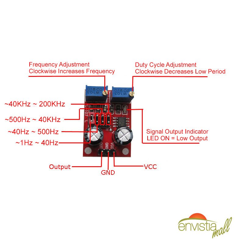
Onboard Controls
- Potentiometer RA: Adjusts the HIGH time of the output waveform (affects both frequency and duty cycle)
- Potentiometer RB: Adjusts the LOW time of the output waveform (affects both frequency and duty cycle)
- Jumper Block (JP): 4-row × 2-pin header that selects the timing capacitor to set the frequency range
🔧 Jumper Settings & Frequency Ranges
The 4-position jumper block selects different timing capacitors to set the approximate frequency range. Place the jumper on only one position at a time, then use the multi-turn potentiometers to fine-tune within the selected range.
| Jumper Position | Capacitor Value | Approximate Frequency Range |
|---|---|---|
| Position 1 | 100 µF | ~1 Hz to ~50 Hz |
| Position 2 | 1 µF | ~50 Hz to ~5 kHz |
| Position 3 | 0.1 µF (100 nF) | ~500 Hz to ~50 kHz |
| Position 4 | 0.001 µF (1 nF) | ~50 kHz to >200 kHz |
Note: Exact frequency ranges will vary between individual modules due to component tolerances. The ranges listed above are approximate and represent typical values.
🚀 Quick Setup
- Connect power: Wire your 5V–15V DC supply to the VCC (+) and GND (−) pins. Do not exceed 15V or reverse polarity.
- Select frequency range: Place the jumper on the position that covers your target frequency (see table above). Only one position should be connected at a time.
- Fine-tune frequency: Adjust the multi-turn potentiometers to dial in your target frequency. Use an oscilloscope, frequency counter, or multimeter with frequency measurement on the OUT pin to verify.
- Adjust duty cycle: Turn potentiometer RA to change the HIGH time and potentiometer RB to change the LOW time. Note that adjusting either will also affect frequency — iterate between both to reach your desired combination.
- Connect output: Wire the OUT pin to your target circuit. Connect the module's GND to your target circuit's ground (common ground is essential). Output amplitude is approximately VCC minus ~1.5V.
🎯 Applications
- Stepper Motor Driver Clock: Generate step pulses for driver boards such as the A4988 or DRV8825 — adjust frequency to control motor speed
- PWM Motor Speed Control: Use the adjustable duty cycle for basic PWM control of DC motors through a MOSFET or motor driver
- LED Dimming: Connect the output through a current-limiting resistor to an LED and adjust duty cycle to control brightness
- Microcontroller Clock / Test Signal: Use as an external clock source or test signal for interrupt handlers, timing routines, or serial communication
- Audio Tone Generator: Produce simple square wave tones in the audible range (~20 Hz to ~20 kHz) for buzzers or speakers
- Circuit Testing & Prototyping: Generate known-frequency signals for testing filters, amplifiers, counters, and other circuits on the workbench
💡 Tips
- Start with the jumper set to the lowest frequency range and work your way up to find the range that best suits your application.
- The multi-turn potentiometers allow very fine adjustments — turn slowly for precise tuning.
- The onboard LED flashes visibly at low frequencies (below ~30 Hz). Above ~30 Hz it appears continuously lit — this is normal. Use a scope or frequency counter to verify output at higher frequencies.
- For stable operation, use a clean, regulated power supply rather than an unfiltered source.
- Frequency and duty cycle are interdependent on this module — adjusting one will affect the other. This is inherent to the NE555 astable circuit design, not a defect.
- In standard astable mode, the minimum duty cycle is approximately 50%. For duty cycles below 50%, an external diode modification would be required (not present on this module).
- For driving higher-current loads, use the output to drive a transistor or MOSFET rather than connecting the load directly to the OUT pin.
📦 What's in the Box
- 1 × NE555 Duty Cycle Adjustable Pulse Frequency Square Wave Signal Generator Module
📄 Documentation & Resources
- User Guide — Setup, Jumper Settings, Frequency Tuning & Applications
- NE555P Precision Timer IC Datasheet (PDF)
- All Logic, I2C, Level Translation & Timing Module User Guides
Sold and supported by Envistia Mall. Ships from the USA. For wiring diagrams, jumper settings, and troubleshooting, see the User Guide linked above. The manufacturer and Envistia LLC (dba Envistia Mall) are not responsible for any damages or losses resulting from the use of this product. Always follow proper electrical safety practices when working with electronic components. Specifications are based on manufacturer data and are subject to change without notice.
Share


Works as it should. Easy to adjust with either an oscilloscope, or a multimeter with frequency meter function. I used this as a tachometer simulator for testing remote start systems on my workbench.
Works great. Very satisfied.
Inexpensive but worked as desired