

NodeMcu V3 LUA WeMos Compatible 32Mb (4MB) Flash 340G ESP8266 IoT Development Module
NodeMcu V3 LUA WeMos Compatible 32Mb (4MB) Flash 340G ESP8266 IoT Development Module
Couldn't load pickup availability
📋 Overview
⚠️ NOTE: This WeMos-compatible NodeMCU WiFi Development board features the same specifications as the standard LoLin NodeMCU V3 board, with the following differences:
✅ The size is reduced to 49 × 26 mm (1.9 x 1.0 inches) from 58 × 31 mm (2.3 x 1.2 inches). The narrow form factor fits on a standard solderless breadboard).
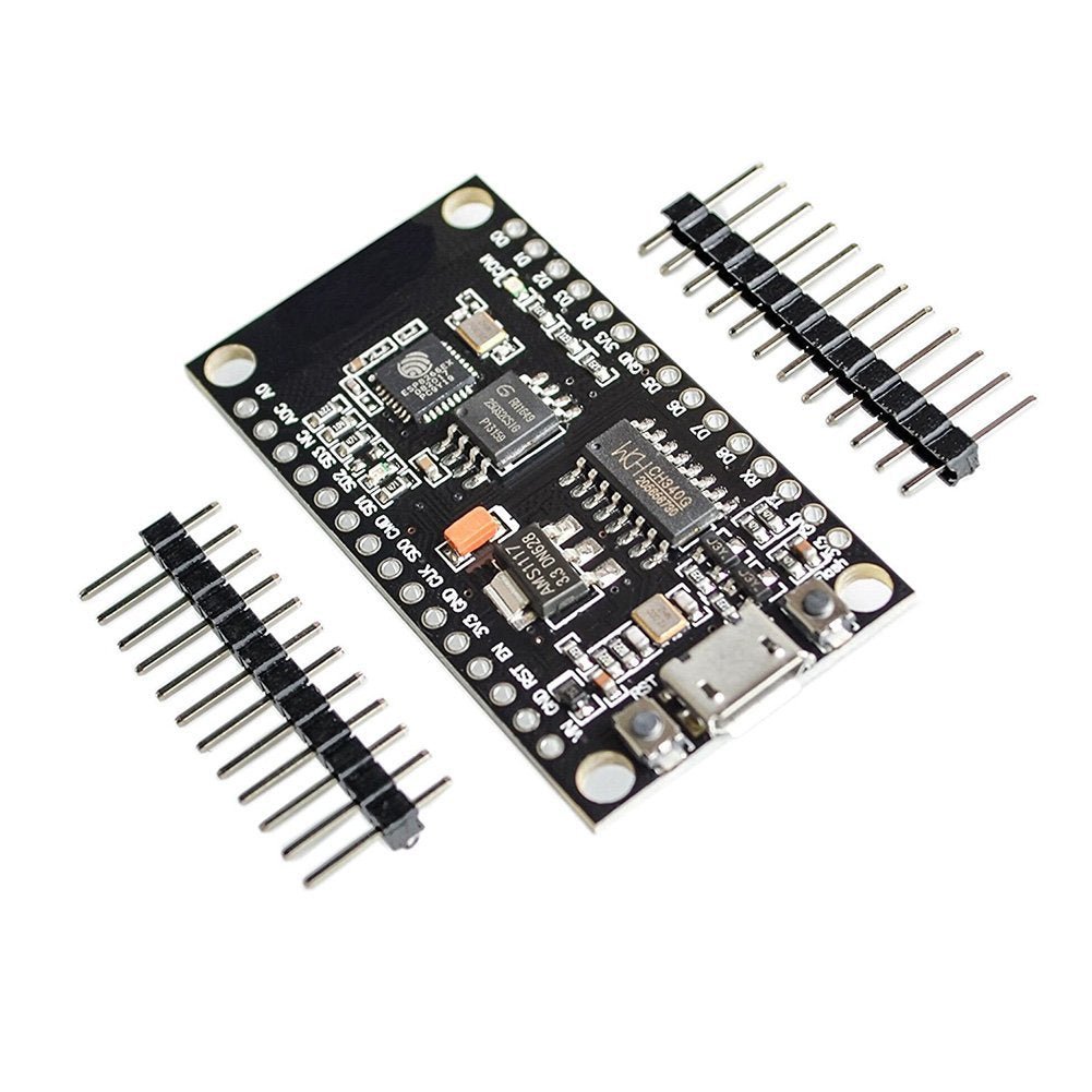
✅ It comes with two sets of 15-pin headers (not already soldered to the board), giving the user the option to use connectors or solder directly.
✅ It does not fit the LoLin Base I/O Expansion Testing Development Breadboard
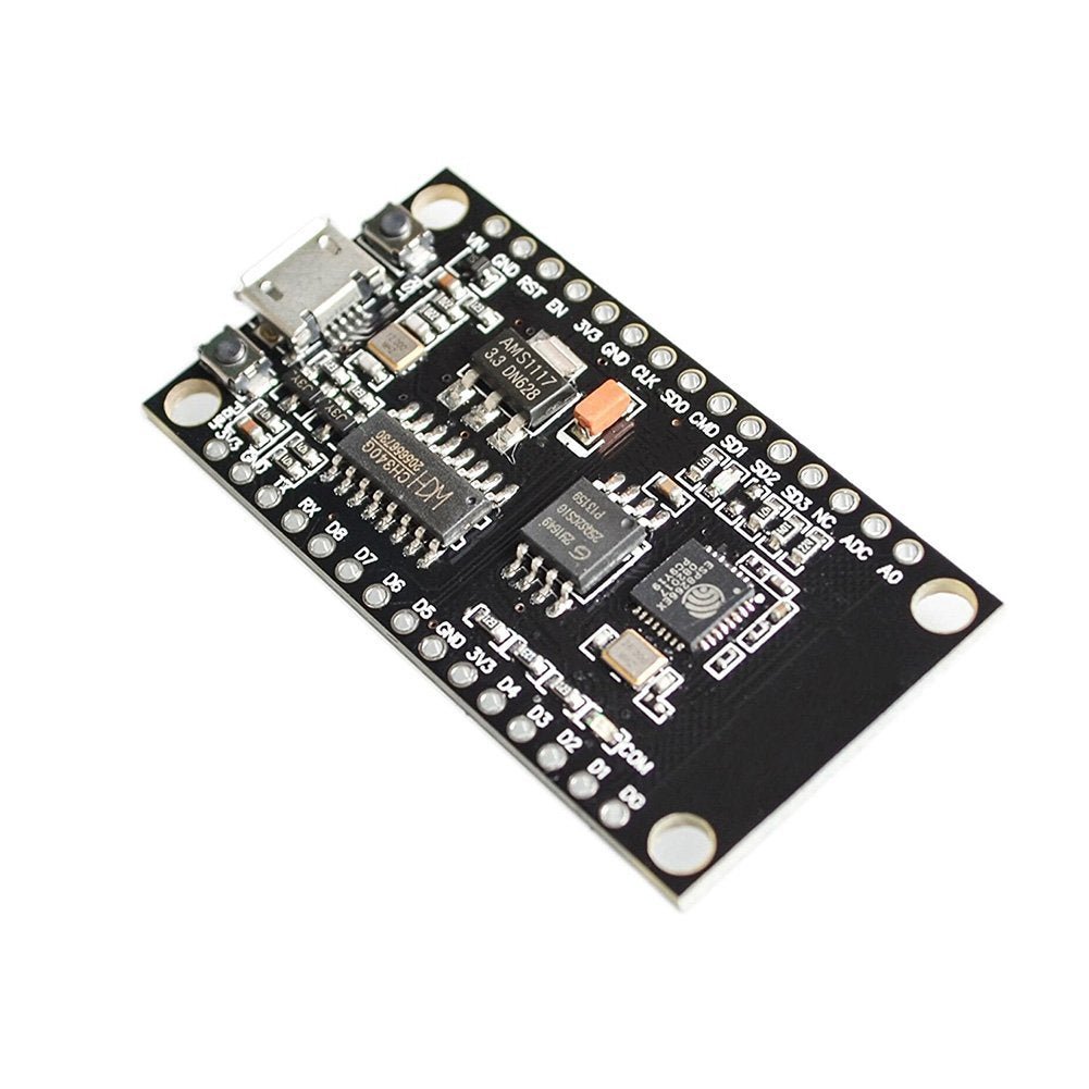
The NodeMCU V3 is an open-source WiFi development board based on the ESP8266 ESP-12E module. It's designed to make IoT development fast and accessible — just plug in a Micro USB cable, install the Arduino IDE board package, and you're ready to build WiFi-connected projects. The board integrates GPIO, PWM, I²C, 1-Wire, SPI, and a single ADC channel all on one compact, breadboard-friendly board.
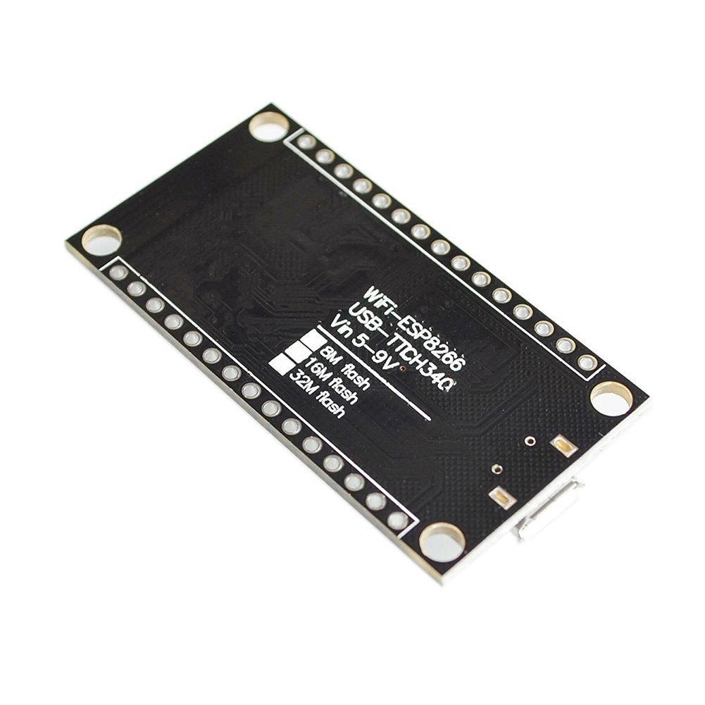
This is the version with the CH340G USB-to-serial chip. It supports three WiFi modes — Station (STA), Access Point (AP), and STA+AP combined — and includes a built-in TCP/IP stack supporting up to 5 simultaneous connections. Program it using the Arduino IDE, NodeMCU/Lua firmware, MicroPython, or PlatformIO.
⚠️ Important: This is a 3.3V logic level board. All GPIO pins operate at 3.3V. Applying 5V to any GPIO pin can permanently damage the ESP8266 chip. If you're connecting 5V sensors or modules, you must use a level shifter. The analog input (A0) has a maximum input voltage of 3.3V.
⭐ Key Features
- Built-In WiFi: ESP8266 ESP-12E module with 802.11 b/g/n WiFi (2.4 GHz)
- Three WiFi Modes: Station (STA), Access Point (AP), and STA+AP combined
- Built-In TCP/IP Stack: Supports up to 5 simultaneous TCP client connections
- Arduino IDE Compatible: Program using the familiar Arduino IDE with the ESP8266 board package
- Multi-Platform Support: Also supports NodeMCU/Lua, MicroPython, and PlatformIO
- 10 Digital GPIO Pins: D0–D8 plus D9/D10 (shared with TX/RX), supporting interrupt, PWM, I²C, and one-wire (except D0)
- 1 Analog Input: 10-bit ADC on pin A0 (3.3V max input)
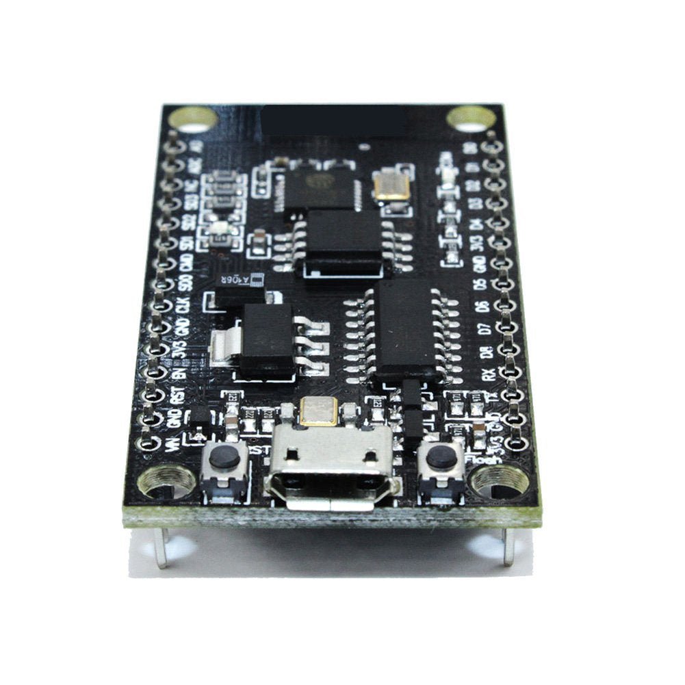
- CH340G USB-to-Serial: Reliable USB programming and serial communication via Micro USB
- OTA Support: Over-The-Air firmware updates via WiFi after initial upload
- Breadboard Friendly: Narrow form factor fits on a standard solderless breadboard (uses both sides). It comes with two sets of 15-pin headers, giving the user the option to use connectors or solder directly
- Compact & Breadboard Friendly: Narrow 49 × 26 mm form factor fits on a standard solderless breadboard
- Unsoldered Headers Included: Two sets of 15-pin headers — choose to use connectors or solder directly
- On-Board Voltage Regulation: 3.3V regulator for the ESP8266
- 80 MHz Processor: ESP8266 running at 80 MHz with 4MB flash memory
📊 Specifications
| Parameter | Value |
|---|---|
| Microcontroller | ESP8266 (Tensilica L106 32-bit) |
| WiFi Module | ESP-12E (802.11 b/g/n, 2.4 GHz) |
| Board Version | NodeMCU V3 |
| Clock Speed | 80 MHz (configurable to 160 MHz) |
| Flash Memory | 4 MB |
| SRAM | 64 KB instruction / 96 KB data |
| Digital I/O Pins | 10 usable GPIO (D0–D8, plus SD1–SD3 reserved) |
| Analog Input | 1 (A0, 10-bit ADC, 3.3V max) |
| GPIO Drive Capability | 15 mA per pin |
| Operating Voltage (Logic) | 3.3V |
| Power Input | 4.5V – 9V (10V max) via VIN, or 5V via Micro USB |
| Operating Current | ~70 mA typical, 200 mA max (WiFi transmission) |
| Standby Current | <200 µA |
| USB-to-Serial Chip | CH340G |
| Serial Baud Rate | 110 – 460,800 bps |
| WiFi Modes | STA / AP / STA+AP |
| TCP Connections | Up to 5 simultaneous clients |
| Board Dimensions | 49 × 26 × 4 mm (1.9 x 1.0 x 0.16 inches) L × W |
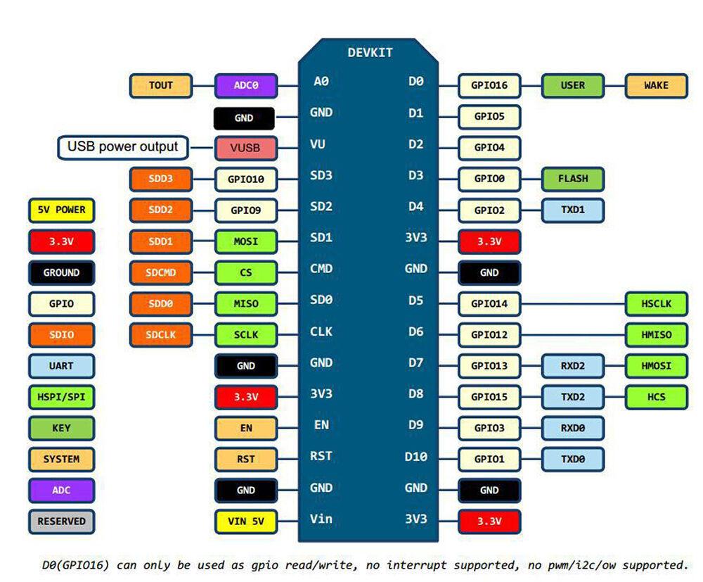
📌 Pinout
The NodeMCU V3 uses labels D0–D10 and A0 printed on the board, but these map to different ESP8266 GPIO numbers internally. This is important when using libraries or code that references GPIO numbers directly.
| Board Pin | ESP8266 GPIO | Function | Notes |
|---|---|---|---|
| D0 | GPIO16 | Digital I/O | No interrupt/PWM/I²C. Deep sleep wake. |
| D1 | GPIO5 | Digital I/O, SCL | Default I²C clock. Safe for general use. |
| D2 | GPIO4 | Digital I/O, SDA | Default I²C data. Safe for general use. |
| D3 | GPIO0 | Digital I/O | Pulled HIGH at boot. LOW = flash mode. |
| D4 | GPIO2 | Digital I/O, Built-in LED | Pulled HIGH at boot. On-board LED (active LOW). |
| D5 | GPIO14 | Digital I/O, SCLK | SPI clock. Safe for general use. |
| D6 | GPIO12 | Digital I/O, MISO | SPI MISO. Safe for general use. |
| D7 | GPIO13 | Digital I/O, MOSI | SPI MOSI. Safe for general use. |
| D8 | GPIO15 | Digital I/O, CS | Pulled LOW at boot. Must be LOW during boot. |
| D9 / TX | GPIO1 | UART TX | Serial transmit. Used during upload. |
| D10 / RX | GPIO3 | UART RX | Serial receive. Used during upload. |
| A0 | ADC0 | Analog Input | 10-bit ADC. Max input: 3.3V. |
💡 Tip — Safest Pins: D1 (GPIO5), D2 (GPIO4), D5 (GPIO14), D6 (GPIO12), and D7 (GPIO13) are the safest pins for general-purpose I/O. They have no boot-mode restrictions and won't interfere with startup or programming. Pins SD1, SD2, and SD3 are connected to the internal SPI flash — do not use them for general I/O.
📦 What's in the Box
- 1× WeMos-compatible NodeMCU V3 32Mbit ESP8266 WiFi IoT Development Board
USB cable is not included. A Micro USB data cable is required for programming and power (charge-only cables will not work).
🔌 Compatible With
- Arduino IDE (with ESP8266 board package installed)
- NodeMCU / Lua firmware
- MicroPython
- PlatformIO
- Standard solderless breadboards (via header pins)
🎯 Typical Applications
- IoT devices and smart home automation
- WiFi-connected web servers and dashboards
- Wireless sensor nodes (temperature, humidity, motion, light)
- MQTT clients for Home Assistant, Node-RED, and other platforms
- Remote data logging and monitoring
- WiFi-controlled relays, LEDs, and actuators
- Weather stations and environmental monitors
- WiFi Access Point and Smart Config provisioning
- Prototyping and learning WiFi-enabled embedded systems
🚀 Getting Started
- Install the CH340G USB driver if your computer doesn't recognize the board when plugged in (Windows 10/11, macOS, and Linux usually include it automatically)
- Open the Arduino IDE and go to File > Preferences. Add this URL to the Additional Board Manager URLs field:
http://arduino.esp8266.com/stable/package_esp8266com_index.json - Go to Tools > Board > Boards Manager, search for esp8266, and install the package
- Select Tools > Board > "NodeMCU 1.0 (ESP-12E Module)"
- Connect the board via Micro USB, select the correct COM port, and upload the Blink example to verify everything works
💡 Tip: The built-in LED is active LOW — writing LOW turns it ON, and HIGH turns it OFF. This is the opposite of most Arduino boards. The ESP8266 only supports 2.4 GHz WiFi — it cannot connect to 5 GHz networks.
See our complete User Guide (link below) for detailed setup instructions, WiFi web server example code, and troubleshooting tips.
⚠️ Important Notes
- 3.3V Logic Level: All GPIO pins are 3.3V. Applying 5V to any pin will permanently damage the ESP8266 chip. Use a level shifter for 5V devices.
- Analog Input Limit: The maximum input voltage on A0 is 3.3V. Exceeding this can damage the ADC.
- VIN Voltage Limit: The VIN pin accepts 4.5V–9V (10V absolute max). Do not exceed 10V.
- Boot Pin Restrictions: D3 (GPIO0), D4 (GPIO2), and D8 (GPIO15) have specific state requirements during boot. Connecting peripherals that pull these pins to the wrong state will prevent the board from starting.
- Reserved Pins: SD1, SD2, and SD3 (GPIO8, 9, 10) are connected to the internal SPI flash. Do not use them for general I/O.
- WiFi is 2.4 GHz Only: The ESP8266 does not support 5 GHz WiFi networks.
- GPIO Current Limit: Each pin can source/sink approximately 15 mA. Use a transistor or MOSFET for higher-current loads.
- Use a Data USB Cable: Many Micro USB cables are charge-only. If the board isn't recognized, try a different cable with data lines.
📄 Documentation & Resources
This product is compatible with the Arduino IDE but is not manufactured by or affiliated with Arduino. "Arduino" is a trademark of Arduino SA. Sold and supported by Envistia Mall. Ships from the USA. For wiring diagrams and troubleshooting, see the User Guide link above. The manufacturer and Envistia LLC (dba Envistia Mall) are not responsible for any damages or losses resulting from the use of this product. Always follow proper electrical safety practices when working with electronic components. Specifications are based on manufacturer data and are subject to change without notice.
Share