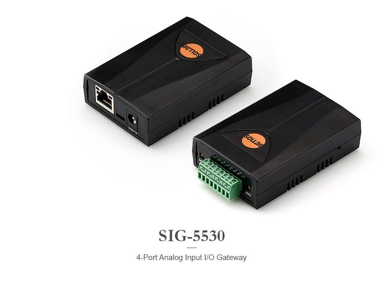
Sollae Systems SIG-5530 4-Port Analog Input Ethernet I/O Gateway with Modbus/TCP
Sollae Systems SIG-5530 4-Port Analog Input Ethernet I/O Gateway with Modbus/TCP
Couldn't load pickup availability
Transform your analog sensors into network-connected smart devices with the Sollae Systems SIG-5530—a professional-grade I/O gateway that brings industrial monitoring into the modern era.
Whether you're monitoring temperature, pressure, flow, or any other analog measurement, the SIG-5530 makes it simple to integrate legacy sensors into your SCADA system, HMI, or monitoring platform using the industry-standard Modbus/TCP protocol.
What Makes the SIG-5530 Essential for Industrial Monitoring?
The SIG-5530 eliminates the complexity of analog sensor integration. Instead of running individual wires back to your control room, simply connect your sensors to the gateway, plug in an Ethernet cable, and access real-time data from anywhere on your network. It's that straightforward.
Key capabilities:
- 4 independent analog input ports that you can configure individually for voltage (0-5V) or current (4-20mA / 0-20mA) measurements
- 16-bit ADC resolution delivering 65,536 discrete values for precise monitoring
- Modbus/TCP protocol for seamless integration with virtually any industrial control system
- Industrial temperature range from -40°C to +85°C for reliable operation in harsh environments
- Multiple simultaneous connections supporting up to 4 TCP sessions at once
SIG-5530 TECHNICAL SPECIFICATIONS
Analog Input Capabilities
- Number of Ports: 4 independent channels
-
Input Types:
- Voltage: 0-5V DC
- Current: 4-20mA (industry standard)
- Current: 0-20mA
- Resolution: 16-bit (0-65,535 values)
- Terminal Block: 3.5mm pitch, 8-pole screw terminals
- 1-bit ADC Function: Convert analog values to digital on/off states for threshold-based control
Network Interface
- Ethernet: 10/100 Mbps auto-sensing (RJ45)
- Cable Support: Straight-through or crossover cables (auto-detect)
- Protocols: Modbus/TCP, TCP/UDP, ICMP, DHCP, mDNS, SSL/TLS
- IP Support: IPv4/IPv6 dual stack
- Connections: Up to 4 simultaneous TCP sessions
- Default Port: 502 (Modbus/TCP standard)
Power Requirements
- Input Voltage: DC 5V ±0.5V
- Current Draw: Typically 264mA
- Protection: Reverse voltage and surge protection built-in
Physical Specifications
- Dimensions: 94mm × 57mm × 24mm (3.7" × 2.2" × 0.9")
- Weight: Approximately 65g (2.3 oz)
- Mounting: Compact design for DIN rail or panel mounting
Environmental
- Operating Temperature: -40°C to +85°C (-40°F to +185°F)
- Storage Temperature: -40°C to +85°C (-40°F to +185°F)
Indicators
- LEDs: RUN (system status), LINK (network connection), MTX (transmit), MRX (receive)
Certifications & Compliance
- CE: EMC 2014/30/EU, RoHS 2011/65/EU
- FCC: Part 15 Subpart B, Class A
- KC: Registration (KN 32, KN 35)
WHAT'S INCLUDED
- SIG-5530 4-Port Analog Input I/O Gateway
- Quick Start Guide
- Free spFinder configuration software (download from manufacturer)
All software is available for download from the Sollae Systems ezTCP website. See the link under the Technical Support & Resources section below.
Note: Power supply (5V DC), Ethernet cable, and sensors sold separately.
KEY FEATURES & BENEFITS
Flexible Input Configuration
Each of the four analog input ports can be independently configured for your specific sensor type. Mix and match voltage and current sensors on the same gateway—perfect for diverse monitoring applications.
True Industrial-Grade Reliability
With an operating temperature range from -40°C to +85°C, the SIG-5530 handles extreme environments that would disable consumer-grade equipment. Built-in reverse voltage and surge protection safeguard your investment.
Modbus/TCP Native Support
No protocol conversion needed. The SIG-5530 speaks Modbus/TCP natively, making integration with PLCs, SCADA systems, and HMIs completely straightforward. Access your sensor data using standard Modbus function codes.
Multiple Simultaneous Connections
Support up to 4 concurrent TCP sessions, allowing your HMI, SCADA system, data logger, and monitoring software to all access the gateway simultaneously without conflicts.
Smart 1-bit ADC Function
Convert analog measurements into digital on/off states based on configurable thresholds. Perfect for alarm conditions, threshold monitoring, or implementing "Internet Switch" functionality to trigger actions on other networked devices.
Easy Configuration & Monitoring
The included spFinder software provides an intuitive interface for:
- Device discovery on your network
- Complete configuration management
- Real-time monitoring of all analog inputs
- Viewing current, minimum, and maximum values
- Firmware updates (online or manual)
- Export/import of configuration settings
Comprehensive Data Access
Access sensor data in multiple formats via Modbus registers:
- Current analog values (16-bit integer or 32-bit floating point)
- Minimum values recorded since last reset
- Maximum values recorded since last reset
- 1-bit ADC states for threshold monitoring
TYPICAL APPLICATIONS
Industrial Automation
Monitor process variables like temperature, pressure, flow rate, and level in manufacturing environments. Integrate seamlessly with existing PLCs and SCADA systems.
Environmental Monitoring
Track temperature, humidity, air quality, and other environmental parameters in facilities, greenhouses, or outdoor installations.
Energy Management
Monitor power consumption, voltage levels, and current draw across electrical systems for energy optimization and predictive maintenance.
HVAC Systems
Integrate temperature, pressure, and airflow sensors into building automation systems for efficient climate control.
Water & Wastewater
Monitor flow rates, pressure, pH levels, and other critical parameters in water treatment and distribution systems.
Data Center Monitoring
Track temperature, humidity, and power parameters across server rooms and equipment racks.
SETUP & CONFIGURATION
Getting Started in 5 Simple Steps:
-
Power Connection
- Connect a 5V DC power supply to the 2-pole power terminal
- Observe the RUN LED to confirm power-up
-
Sensor Wiring
- Connect your analog sensors to the 8-pole terminal block
- Configure each port for voltage (0-5V) or current (4-20mA / 0-20mA) input
-
Network Connection
- Connect an Ethernet cable from your network to the RJ45 port
- The gateway supports both DHCP (automatic IP) and static IP addressing
-
Configuration
- Download and install the free spFinder software
- Search for the device on your network
- Log in (default ID: sig-5530, password: sig-5530)
- Configure network settings, TCP parameters, and analog input modes
-
Integration
- Access sensor data via Modbus/TCP from your SCADA system or monitoring software
- Use standard Modbus function codes to read registers
Default Settings:
- Login ID: sig-5530
- Password: sig-5530 (change immediately for security)
- Network: DHCP enabled by default
- TCP Port: 502 (Modbus/TCP standard)
- Connection Mode: TCP Server
- Analog Input Mode: 0-5V (all ports)
MODBUS REGISTER MAP
The SIG-5530 provides comprehensive data access through Modbus/TCP registers:
Read-Only Registers:
- Analog Input Values (16-bit integer format)
- Minimum Values (since last reset)
- Maximum Values (since last reset)
- Analog Input Values (32-bit floating point format)
- 1-bit ADC States (digital on/off values)
- Device Information (model, firmware version, uptime, etc.)
Read/Write Registers:
- Reset Min/Max Values (clear recorded minimums and maximums)
- Notification Enable (configure event notifications)
Complete register addresses and function codes are detailed in the included user manual.
ADVANCED FEATURES
Internet Switch Functionality
The 1-bit ADC function enables sophisticated automation scenarios. Set high and low reference thresholds for each analog input, and the gateway converts continuous measurements into digital states. Use these states to trigger actions on other networked devices without requiring a central HMI.
Example: When a temperature sensor exceeds a threshold, the gateway can signal a relay module to activate cooling equipment—all without human intervention.
Security Features
- Password Protection: Secure access to configuration settings
- SSL/TLS Support: Encrypted communications for sensitive data
- IP Filtering: Restrict access to authorized hosts only
- Remote Access Control: Enable/disable remote configuration as needed
Diagnostic Capabilities
- Real-time Statistics: Monitor TCP connection states, Modbus frame counts, and data throughput
- Communication Logging: Track all Modbus queries, responses, and errors
- LED Indicators: Visual feedback for power, network link, and data transmission
COMPATIBLE SENSORS
The SIG-5530 works with any analog sensor that outputs:
Voltage Sensors (0-5V)
- Temperature sensors (thermocouples with signal conditioning)
- Potentiometric sensors
- Analog output modules
- Variable resistor sensors
Current Loop Sensors (4-20mA / 0-20mA)
- Industrial pressure transmitters
- Flow meters
- Level sensors
- pH sensors
- Humidity transmitters
- Any 2-wire or 3-wire current loop sensor
FREQUENTLY ASKED QUESTIONS
Q: Can I mix voltage and current sensors on the same gateway?
A: Yes! Each of the 4 ports can be independently configured for voltage (0-5V) or current (4-20mA / 0-20mA) input. Configure them individually based on your sensor requirements.
Q: What software do I need to read the sensor data?
A: Any Modbus/TCP client software will work. Popular options include ModScan, QModMaster, or integration directly into your SCADA system (Ignition, Wonderware, etc.). The free spFinder software is used for configuration and monitoring.
Q: How do I access the gateway remotely over the internet?
A: Configure port forwarding on your router to forward external traffic to the gateway's IP address and port 502. For enhanced security, use a VPN connection instead of direct internet exposure. Remote access can be enabled/disabled in the security settings.
Q: What's the difference between 4-20mA and 0-20mA current inputs?
A: 4-20mA is the industrial standard where 4mA represents 0% of the measurement range and 20mA represents 100%. This "live zero" allows detection of broken wires (0mA). 0-20mA uses the full range from 0-100% but cannot detect wire breaks.
Q: Can multiple devices access the gateway simultaneously?
A: Yes, the SIG-5530 supports up to 4 simultaneous TCP connections, allowing your HMI, SCADA system, data logger, and monitoring software to all connect at the same time.
Q: What power supply do I need?
A: You need a regulated 5V DC power supply capable of at least 300mA (the gateway typically draws 264mA). Ensure the power supply is within the ±0.5V tolerance (4.5V to 5.5V).
Q: How accurate are the analog measurements?
A: The SIG-5530 uses a 16-bit ADC providing 65,536 discrete values across the input range. For a 0-5V input, this gives approximately 76μV resolution. Actual accuracy depends on your sensor specifications and environmental factors.
Q: Can I use this outdoors?
A: The SIG-5530 operates reliably from -40°C to +85°C, but it should be installed in a weatherproof enclosure if used outdoors to protect against moisture and physical damage.
TECHNICAL SUPPORT & RESOURCES
SIG-5530 4-Port Analog Input I/O Gateway Product Page
SIG-5530 4-Port Analog Input I/O Gateway Datasheet
SIG-5530 4-Port Analog Input I/O Gateway User Manual
ModBus/TCP Protocol ezTCP Application Note
SIG Series I/O Applications (Internet Switch) Application Note
spFinder Management Program for Packageware Products (for Windows) Download
ModMap HMI Application for Remote I/O Gateway (Supports Modbus/TCP) Download
The SIG-5530 is designed for professional industrial applications. Basic networking knowledge and familiarity with Modbus/TCP protocol recommended for optimal deployment.
Share