


AMS1117 3.3V and 5V Module Output Current vs Voltage Safe Operating Area (SOA) Curves
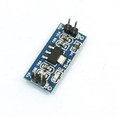 Our AMS1117 3.3V and 5V voltage regulator modules are rated at 1 Amp maximum output current. However it is a linear regulator, not a switching converter. This means it will dissipate a lot of heat if it is asked to handle a higher current with a large voltage drop.
This should be taken into account in your circuit design, as the module will not be able to achieve the full 1A output when the input to output voltage differential is greater than a couple of volts.
We have developed these Safe Operating Area (SOA) curves to assist in your design, and to help determine whether these linear voltage regulator modules are an appropriate solution for your application.
AMS1117 Power Dissipation
The Power Dissipation of the AMS1117 linear voltage regulator is calculated using the formula:
Pd = (Vin - Vout)*Iout
where Pd is Power Dissipation, Vin is Input Voltage to the module, Vout is the module Output Voltage, and Iout is the Output Current.
Plugging in a couple of example numbers, assume you want to use an AMS1117-5V module to power a 5V USB-powered electronic gadget from a 12V car battery, and your gadget requires 500mA current to operate.
The power dissipated in the AMS1117 regulator would be:
Pd=(12V - 5V)*500mA
Pd = 7*0.5 = 3.5W
Intuition tells me that dissipating 3.5W from such as small device and circuit board is going to be a problem. But how much of a problem?
AMS1117 Maximum Junction Temperature Calculations
Referring to the AMS1117 data sheet, the maximum junction temperature of the device is 125 degrees C.
Junction temperature is calculated using the formula:
Tj = Ta(max) + Pd(Thermal Resistance (junction-to-ambient))
where Tj is Junction Temperature, Ta is maximum ambient temperature, and Pd is Power Dissipation defined above.
Based on Table 1 in the AMS1117 data sheet, I estimate this module to have a Thermal Resistance (Junction to Ambient) of about 70 degrees C per Watt.
Assuming a maximum ambient temperature of 25C, the maximum output current for the device can be calculated using the formula:
125C = 25C + Pd(70C) or
100 = Pd*70
Solving for Pd, the device's maximum Power Dissipation at 25C ambient should not exceed 100/70 = 1.4 Watts.
Therefore in the example above (12V input at 500mA output), the power dissipation of 3.5W is in excess of the maximum 1.4W rating, and a different option, such as a switching buck converter, should be considered.
AMS1117 Voltage Regulator Module SOA Curves
Given these data, the safe Operation Area (SOA) curves below should provide a general indication of the maximum output current that you can expect to provide for a given input voltage for both the 5V AMS1117-5 and 3.3V AMS1117-3.3 modules at 25 degrees C ambient temperature. Above 25C, the devices will need to be further derated, or additional cooling provided. Below 25C, the output current can be increased.
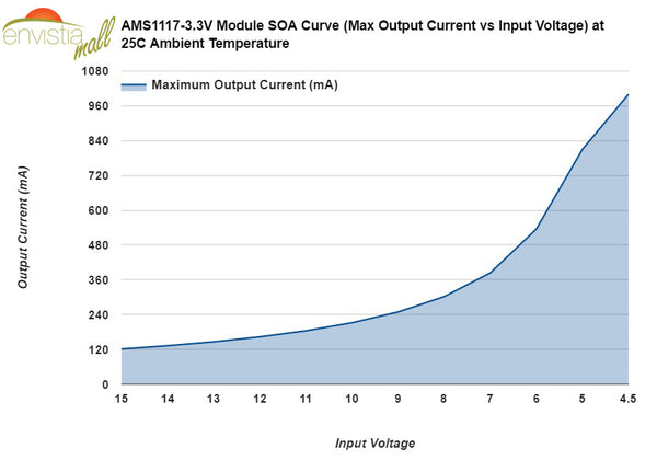
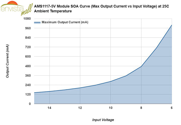
In conclusion, to maximize the output current of the module, use the minimum input voltage possible for the largest safety margin. The AMS1117 regulator device can operate down to a 1V differential voltage, so for the 5V output module, 6 or 6.5V input would be the best choice - or 4.5-5V input if you are using the 3.3V output module.
Disclaimer:
These curves are based upon maximum junction temperature and thermal resistance calculations, and have not been verified through testing. The device's thermal resistance installed in this module has been estimated using data from the AMS1117 data sheet, but has not been validated through testing. Your actual mileage may vary.