QSD124 Infrared (IR) Phototransistor 880nm 5mm – Daylight Filter, Narrow Beam – onsemi
QSD124 Infrared (IR) Phototransistor 880nm 5mm – Daylight Filter, Narrow Beam – onsemi
No se pudo cargar la disponibilidad de retiro
🧭 Product Description
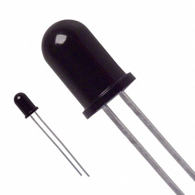
The QSD124 is a high-sensitivity silicon infrared phototransistor manufactured by onsemi (formerly ON Semiconductor). Encapsulated in an infrared-transparent black plastic T-1 3/4 (5mm) package with a built-in daylight filter, it detects infrared light at a peak wavelength of 880nm while rejecting visible ambient light — making it ideal for reliable IR detection in real-world lighting conditions.
The QSD124 features a narrow ±12° reception angle (24° total) for precise, directional IR sensing, and delivers a strong 6 mA typical on-state collector current at 0.5 mW/cm² irradiance — the highest sensitivity variant in the QSD12X family.
When paired with a matched QED123 IR emitter LED (sold separately), the QSD124 forms a complete infrared transmitter/receiver pair suitable for object detection, counting, proximity sensing, optical switches, and wireless IR communication.
✅ Key Features
- Peak Sensitivity: 880nm — optimized for near-infrared detection
- Built-in Daylight Filter: Black epoxy package blocks visible light, reducing false triggers from ambient lighting
- Narrow Reception Angle: ±12° (24° total) for focused, directional detection
- High Sensitivity: 6 mA typical on-state collector current (highest in QSD12X family)
- Fast Response: 7 µs typical rise and fall times
- Low Dark Current: 100 nA max at VCE = 10V — minimal noise when no IR is present
- Wide Operating Range: -40°C to +100°C
- Standard T-1 3/4 (5mm) Package: Easy breadboard and through-hole PCB mounting
- Matched Emitter Available: Designed to pair with QED123 / QED22X / QED23X IR LEDs
- Pb-Free / RoHS Compliant
- Manufacturer: onsemi (formerly ON Semiconductor)
📊 Specifications
| Parameter | Symbol | Value | Unit |
|---|---|---|---|
|
Peak Sensitivity Wavelength
|
λPS
|
880
|
nm
|
|
Reception Angle
|
Θ
|
±12 (24° total)
|
°
|
|
Collector-Emitter Voltage (max)
|
VCE
|
30
|
V
|
|
Emitter-Collector Voltage (max)
|
VEC
|
5
|
V
|
|
On-State Collector Current (typ)
|
IC(ON)
|
6 (typ), 29 (max)
|
mA
|
|
Collector-Emitter Dark Current (max)
|
ICEO
|
100
|
nA
|
|
Collector-Emitter Breakdown Voltage
|
BVCEO
|
30 (min)
|
V
|
|
Emitter-Collector Breakdown Voltage
|
BVECO
|
5 (min)
|
V
|
|
Saturation Voltage
|
VCE(SAT)
|
0.4 (max)
|
V
|
|
Rise Time (typ)
|
tr
|
7
|
µs
|
|
Fall Time (typ)
|
tf
|
7
|
µs
|
|
Power Dissipation
|
PD
|
100
|
mW
|
|
Operating Temperature
|
TOPR
|
-40 to +100
|
°C
|
|
Storage Temperature
|
TSTG
|
-40 to +100
|
°C
|
|
Package
|
—
|
T-1 3/4, 5mm (Case 100CE)
|
—
|
|
Package Material
|
—
|
Black Epoxy (IR transparent)
|
—
|
Test conditions for IC(ON) and VCE(SAT): Ee = 0.5 mW/cm², VCE = 5V, λ = 880nm AlGaAs source.
Power dissipation derated linearly at 1.33 mW/°C above 25°C.
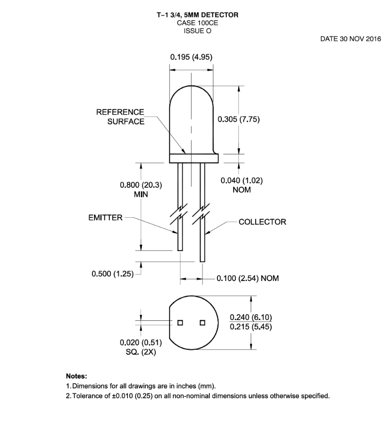
🔌 Pin Configuration
The QSD124 is a 2-lead device in a standard T-1 3/4 (5mm) radial package:
| Pin | Function |
|---|---|
|
Longer Lead
|
Collector (C)
|
|
Shorter Lead
|
Emitter (E)
|
|
Flat on Package Base
|
Indicates Emitter side
|
Note: The flat edge on the base of the package identifies the emitter lead. When viewed from the top, the flat is on the emitter side.
🔧 Typical Circuit Connection
The QSD124 is typically used in a common-emitter configuration:
- Connect the Collector (longer lead) to your supply voltage (VCC) through a load resistor (RL)
- Connect the Emitter (shorter lead) to Ground (GND)
- Take your output signal from the junction of the collector and load resistor
Choosing a Load Resistor:
- For digital (on/off) detection: 10 kΩ to 100 kΩ — higher values increase sensitivity but slow response
- For analog measurement: 1 kΩ to 10 kΩ — provides a voltage proportional to IR intensity
- For fastest response: 100 Ω (as specified in datasheet rise/fall time test conditions)
Example — Basic IR Detection with Arduino/Microcontroller
VCC (3.3V or 5V) ──── RL (10kΩ) ──┬──── Analog/Digital Input Pin
│
QSD124 Collector
QSD124 Emitter
│
GND
Terminology note: "Collector" and "Emitter" here refer to the pin names of the QSD124 phototransistor — standard terminology for any transistor. These are not references to the QED123 IR emitter LED, which is a separate component that would be positioned opposite the QSD124 to provide the infrared light source.
When IR light hits the QSD124, it conducts and pulls the output voltage LOW. When no IR is present, the output is pulled HIGH through the load resistor.
🛠️ Common Applications
- Object / Presence Detection — Detect objects breaking an IR beam (paired with QED123 IR emitter LED)
- Optical Counters — Count items on a conveyor or production line
- Proximity Sensors — Detect nearby objects via reflected IR
- Optical Encoders — Rotary and linear position sensing
- Optical Switches / Interrupters — Slotted optical switch applications
- IR Remote Control Receivers — Receive IR signals from remote controls
- Line-Following Robots — Detect dark/light surfaces using reflected IR
- Safety Barriers / Light Curtains — Detect beam interruption for safety systems
- Wireless IR Communication — Short-range data transmission via modulated IR
- Tachometers / RPM Counters — Measure rotational speed via reflected or interrupted IR
🔄 QSD123 vs. QSD124 — Which Do You Need?
Both are in the same family with identical packages and pinouts. The difference is sensitivity:
| Parameter | QSD123 | QSD124 |
|---|---|---|
|
IC(ON) Typical
|
4 mA
|
6 mA
|
|
IC(ON) Range
|
4–16 mA
|
6–29 mA
|
|
Best For
|
Shorter range, brighter IR sources
|
Longer range, weaker IR sources, higher sensitivity applications
|
Choose the QSD124 (this product) when you need maximum sensitivity — for longer detection distances, weaker IR sources, or applications where you want the strongest possible signal.
⚠️ Important Notes
- Polarity matters. Reversing collector and emitter leads will result in no detection or damage. Identify the flat on the package base (emitter side) before soldering.
- Do not exceed 30V VCE or 100 mW power dissipation (derate above 25°C at 1.33 mW/°C).
- Daylight filter is not absolute. The black epoxy package significantly reduces visible light sensitivity, but extremely bright direct sunlight or high-intensity visible light sources may still cause some photocurrent. For best results in bright environments, use modulated IR (pulsed) with a matched receiver circuit.
- Soldering: Use RMA flux. Keep soldering iron tip at least 1.6mm (1/16") from the housing. Iron soldering: 240°C max for 5 seconds. Flow soldering: 260°C max for 10 seconds.
- Not for life-support or medical implant applications per onsemi guidelines.
📦 What's in the Box
- 1, 2, 5, or 10 QSD124 Infrared Phototransistors (onsemi)
Matched emitter LED: The QED123 IR emitter LED, purchased separately, is the recommended paired emitter for this phototransistor.
📘 Resources
- Datasheet: QSD124/D (Rev. 3, August 2023)
- Matched Emitters: QED123, QED223, QED233
Share