CHIPSEN BoT-nLE521DU Bluetooth v5.0 BLE Class2 (+4dBm) DIP Slave Module w/ Chip + U.FL Antenna & Pin Headers
CHIPSEN BoT-nLE521DU Bluetooth v5.0 BLE Class2 (+4dBm) DIP Slave Module w/ Chip + U.FL Antenna & Pin Headers
Couldn't load pickup availability
Please CONTACT US for OEM and Quantity Discounts.
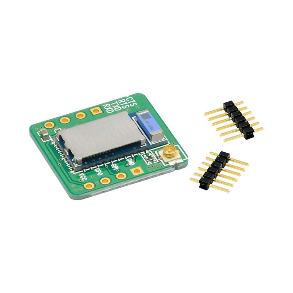
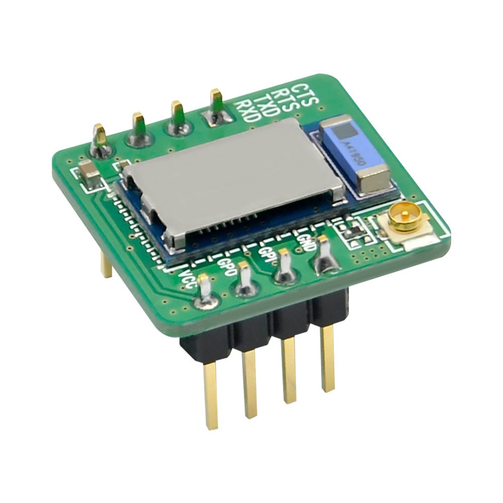
The CHIPSEN BoT-nLE521DU module features a BoT-nLE521 SMD slave-mode module mounted on a DIP carrier with 2.54mm headers pins and a U.FL antenna connector. This module can be installed in through-hole PCBs, mounted in 2.54mm sockets for easy removal, or can be plugged into the CHIPSEN BoT-USB-TB Test Board to easily connect the module to a PC's USB port.
The electrical and performance specifications for this module are the same as the BoT-nLE521. See the BoT-nLE521 OEM module product page for full specifications.

BoT-nLE521DU Features
- Bluetooth Processor: BoT-nLE521 (Slave Mode)
- BT Version: Bluetooth Low Energy (BLE) V5
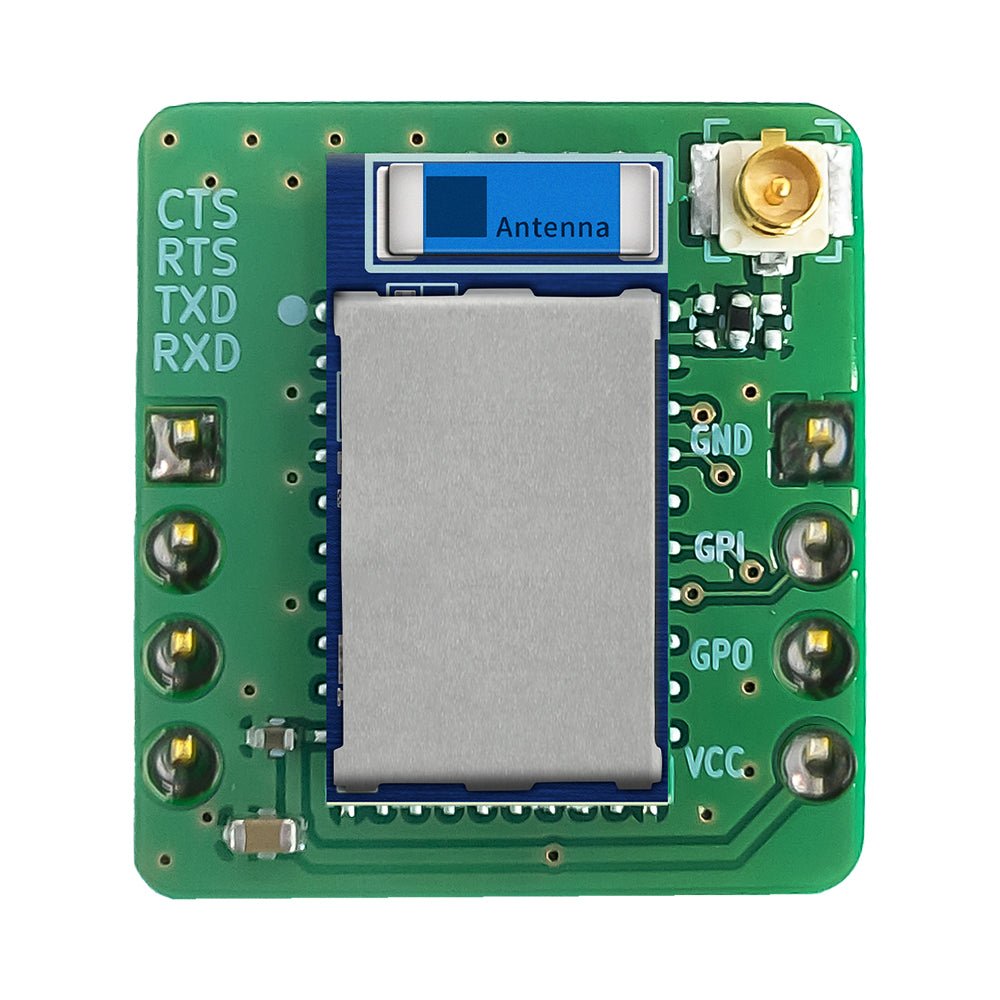
- Antenna: Chip Antenna + U.FL Antenna Connector (U.FL antenna is not included)
- ARM® Cortex®-M4 32-bit processor with FPU, 64 MHz
- Memory: 192 kB Flash / 24 kB RAM
- RF Output Power: MAX +4 dBm (-20 ~ 4 dBm)
- RF Receive Sensitivity: -96 dBm
- Type 2 near field communication (NFC-A) tag with wakeup-on-field and touch to-pair capabilities
- Fully automatic LDO and DC/DC regulator system (Uses LDO by Default)
- Temperature Sensor
- UART (CTS/RTS) with EasyDMA, SPI, and I2C data interfaces
- 12-Bit 200 ksps ADC with - 8 configurable channels with programmable gain
- Size: 18 mm x 19 mm x 11 mm (including the header pins)
- Operating Voltage: 1.7V to 3.6V
- Operating Temperature: -40 to +85℃
- RoHS compliant 1.4
- Certifications: SIG, KC (including wireless EMC), IC, FCC, CE, TELEC
BoT-nLE521DU Header Pins, Pinout and U.FL Antenna
The BoT-nLE521DU is supplied with unsoldered 2.54mm header pins. The board can be wired into the circuit through the connection pads, or the header pins can be soldered in to plug the board into another PCB, plugged into a BoT-USB-TB Test Board.
The BoT-nLE521DU by default uses the built-in chip antenna. To use an antenna connected to the U.FL connector, install the jumper across the open pads directly below the antenna connector. This will connect the U.FL connector to the output of the Bluetooth module.


Documentation and Downloads
BoT-nLE521 Datasheet and Installation Documentation (PDF)
BoT-nLE521 FCC Certification (PDF)
Share


