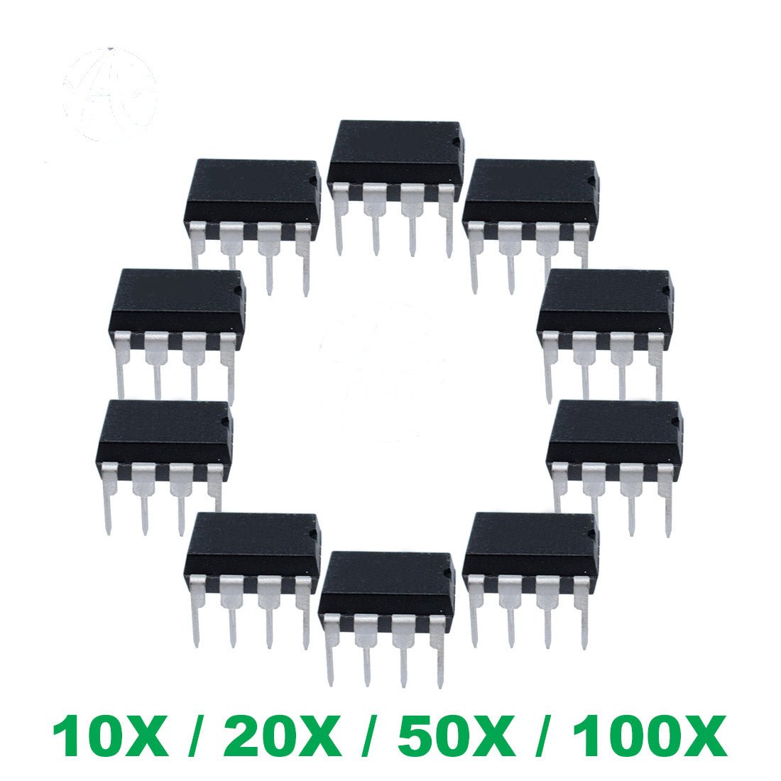
NE555P NE555 DIP-8 TI High Precision Oscillator Timer IC 555 10/20/50/100 Pcs
NE555P NE555 DIP-8 TI High Precision Oscillator Timer IC 555 10/20/50/100 Pcs
Couldn't load pickup availability
📋 Overview
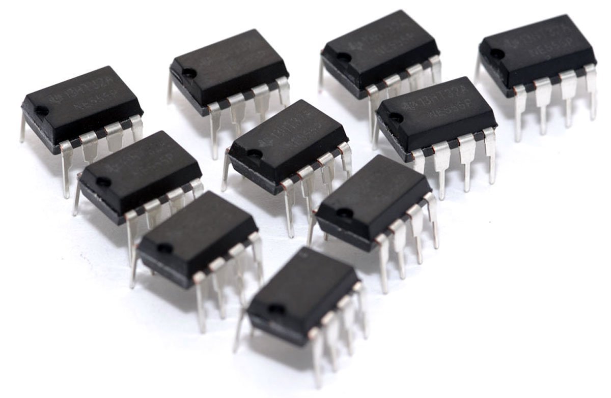
The NE555P is Texas Instruments' legendary precision timer IC in a breadboard-friendly DIP-8 package. First introduced in 1973 and still one of the most popular ICs ever made, the 555 timer generates accurate time delays or free-running oscillations using just a few external resistors and capacitors. It operates from 4.5 V to 16 V and can sink or source up to 200 mA — enough to directly drive LEDs, small relays, buzzers, and TTL logic.
⭐ Key Features
- Two Operating Modes: Monostable (one-shot timer) and astable (free-running oscillator)
- Wide Supply Range: 4.5 V to 16 V
- High Output Current: Sinks or sources up to 200 mA
- Flexible Timing: Microseconds to hours, set by external R and C values
- Adjustable Duty Cycle: Independent control of high and low output times
- TTL Compatible: Output directly drives TTL logic at 5 V
- Supply-Independent Timing: Timing accuracy is determined by external components, not supply voltage
- Active-Low Reset: Dedicated RESET pin overrides all other inputs
📊 Specifications
| Manufacturer | Texas Instruments (TI) |
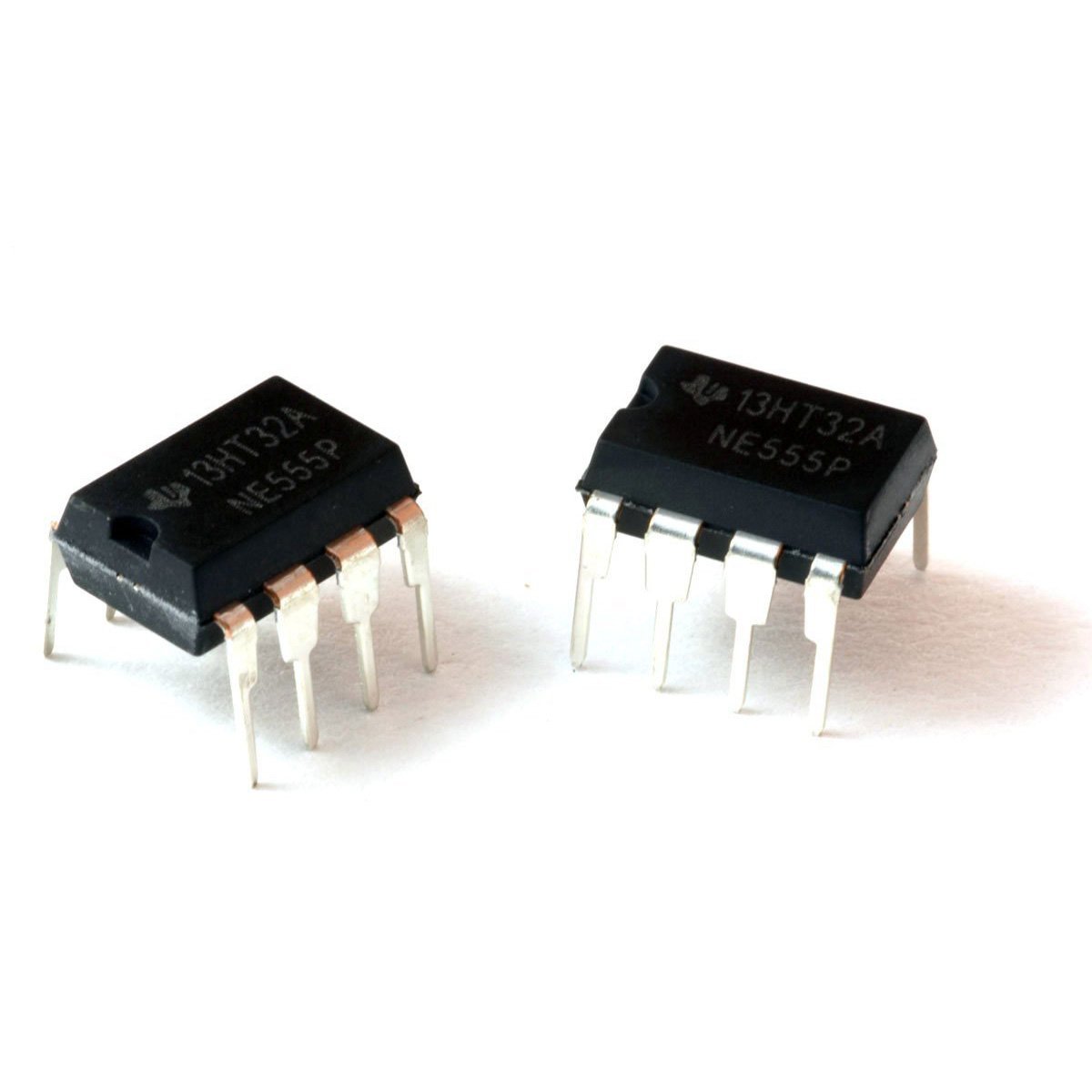
| Part Number | NE555P |
| Package | PDIP-8 (DIP-8 through-hole) |
| Supply Voltage (VCC) | 4.5 V to 16 V |
| Output Current (Sink/Source) | ±200 mA max |
| Timing Range | Microseconds to hours |
| Timing Accuracy | 1% monostable / 2.25% astable (typical) |
| Temperature Coefficient | 50 ppm/°C (typical, monostable) |
| Supply Current (No Load) | 3–6 mA at 5 V / 10–15 mA at 15 V |
| Operating Temperature | 0°C to 70°C |
| Package Dimensions | Approx. 9.81 × 6.35 mm (0.39 × 0.25 inches) |
⚠️ Important: Do not exceed 16 V on the supply pin (VCC). Always tie the RESET pin (pin 4) to VCC if not used, and bypass the CONT pin (pin 5) with a 10 nF capacitor to ground for stable operation.
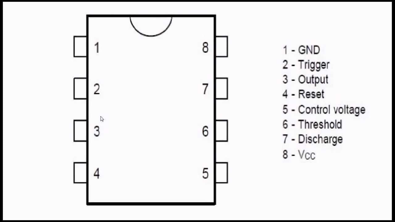
📌 Pinout
| Pin | Name | Function |
|---|---|---|
| 1 | GND | Ground (0 V reference) |
| 2 | TRIG | Trigger — starts timing when pulled below 1/3 VCC |
| 3 | OUT | Timer output |
| 4 | RESET | Active-low reset — tie to VCC if not used |
| 5 | CONT | Control voltage — bypass to GND with 10 nF capacitor |
| 6 | THRES | Threshold — ends timing when voltage exceeds 2/3 VCC |
| 7 | DISCH | Discharge — discharges the timing capacitor |
| 8 | VCC | Supply voltage: 4.5 V to 16 V |

🎯 Typical Applications
- LED flasher / blinker circuits
- Tone generator and buzzer driver
- Pulse-width modulation (PWM) for motor speed or LED brightness control
- Switch debounce circuits
- Timed relay driver
- Missing pulse detector
- Frequency divider
- Precision timing for sensor interfaces
📦 What's in the Box
- NE555P Precision Timer IC (DIP-8) — quantity per selected option
💡 NOTE: These are genuine, factory-sourced TI (Texas Instruments) NE555P devices.
🚀 Getting Started
- Insert the NE555P into your breadboard or PCB socket with pin 1 (GND) at the bottom-left (notch/dot facing up)
- Connect pin 8 (VCC) to your power supply (4.5–16 V) and pin 1 (GND) to ground
- Tie pin 4 (RESET) to VCC if not using the reset function
- Connect a 10 nF ceramic capacitor from pin 5 (CONT) to ground
- Wire your timing resistors and capacitor for monostable or astable mode (see User Guide for formulas and circuit diagrams)
💡 Tip: See our complete User Guide (link below) for detailed pinout tables, timing formulas for both operating modes, and wiring best practices.
⚠️ Important Notes
- Do not exceed 16 V on VCC — exceeding this can permanently damage the IC
- Input voltages on CONT, RESET, THRES, and TRIG must not exceed VCC
- The NE555P draws several milliamps of quiescent current — for battery-powered applications, consider the CMOS version (TLC555 or ICM7555)
- When driving inductive loads (relays, motors), always use a flyback diode to protect the IC
- Follow standard ESD handling precautions when working with the IC
📄 Documentation & Resources
Sold and supported by Envistia Mall. Ships from the USA. For wiring diagrams, setup instructions, and troubleshooting, see the User Guide. The manufacturer and Envistia LLC (dba Envistia Mall) are not responsible for any damages or losses resulting from the use of this product. Always follow proper electrical safety practices when working with electronic components. Specifications are based on manufacturer data and are subject to change without notice.